


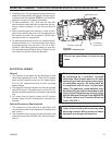
HBDV7 Series Direct Vent Gas Fireplace
54D8000
7
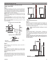
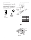
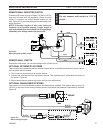
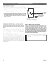
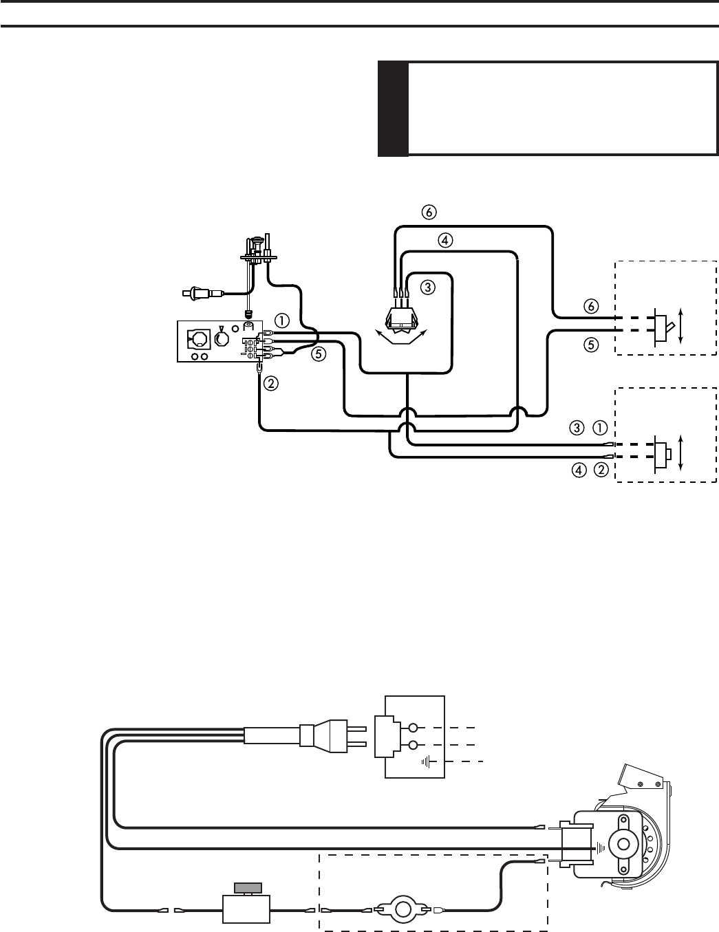
A remote wall switch and up to fifteen (15) feet of 18 Ga.
wire may be used with this appliance. Attach the wall
switch in a junction box at the desired location on the
wall. Figure 45. Do not extend beyond the wall switch wire
length provided.
Figure 45 -
Wiring Diagram for Wall Switch
Position the wall switch. Do not extend beyond the 15 feet of wire.
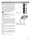
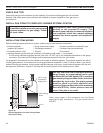
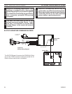
These instructions replace the section entitled Hearth Mount in the Millivolt hand held remote instruc-
tions supplied with the remote.
1. Plug in remote connector wire to remote receiver.
. Connect the wire terminal from the remote receiver. This replaces the 15' wall switch connection to
the switch. Figure 46
3. Mount remote control receiver at junction box (for your wall switch).
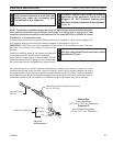
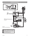
The junction box for the fan/blower systems has been factory installed. This system requires that 110-
10V AC to be wired to the factory installed junction box before the fireplace is permanently installed.
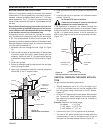
Figure 46
BLACKBLACKWHITE
GREEN
BLACK
BLACKBLACK
Receptacle
Junction
Box
120VAC
Optional Thermostatic Switch
Speed Control
FP2101
BDV blower wiring
Receptacle
Junction
Box
10VAC
Optional Thermostatic Switch
Speed Control
Figure 46 -
Blower Wiring Diagram
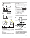
ON
OFF
OPTIONAL REMOTE
WALL SWITCH
ON
OFF
OPTIONAL REMOTE
WALL SWITCH
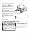
PILOT
HI
LO
ON
OFF
TH
TP
TH/TP
ON
OFF
RS
FP1980
Dv wiring diagram
White
Black
Blue
Gray
Black
Blue
Black