


20 71D0532
ELECTRICAL WIRING
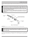
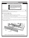
A. COMPLETE MILLI-VOLT SYSTEM CHECK
(“A” Reading - Thermostat contacts CLOSED - Control Knob “ON” - Main burner should turn ON)
a. If the reading is more than 100 milli-volts and the automatic valve still does not come on, replace the control.
b. If the closed circuit reading (“A” reading) is less than 100 millivolts, determine cause for low reading, proceed
to Section B below.
B. Thermopile Output Reading Check
(“B” Reading - Thermostat contacts OPEN - Main burner OFF)
1. Check gas pressure to the unit. If gas pressure is within minimum and maximum on data plate, then check pilot
voltage, 325 millivolts minimum. If the minimum milli-volt reading is not obtainable, replace pilot.
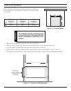
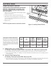
CONNECT SWITCH OR
CHECK TO METER THERMOSTAT METER
TEST TEST LEADS TO CONTACTS READING
TERMINALS SHOULD BE
A COMPLETE 2 & 3 CLOSED CLOSED
SYSTEM
B THERMOPILE 1 & 2 OPEN OPEN
OUTPUT
CHECKING SYSTEM OPERATION
The milli-volt system and individual
components may be checked with a milli-
volt meter having a 0-1000 mV range.
Conduct each check shown in chart below
by connection meter test leads to terminals
as indicated.
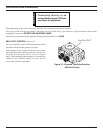
CONNECTING REMOTE RECEIVER
THESE INSTRUCTIONS SUPERCEDE THE SECTION
ENTITLED “HEARTH MOUNT” IN THE MILLI-VOLT
HAND-HELD REMOTE INSTRUCTIONS SUPPLIED
WITH THE REMOTE.
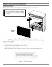
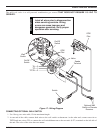
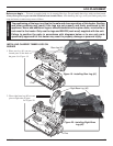
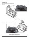
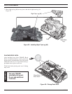
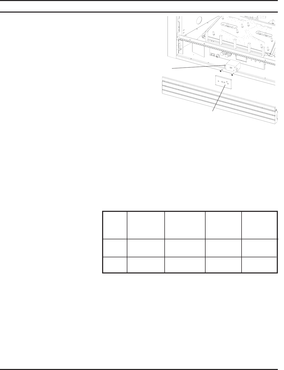
1. Remove cover on control panel to show opening for remote
receiver. See Figure 18.
2. Connect the remote connectors located in the unit.
3. Slide remote receiver in the opening of control panel. Use
two screws provided to attach remote receiver to the control
panel. See Figure 18.
4. Replace Cover.
NOTE: Do not place remote in combustion chamber.
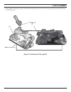
Figure 18 - Installing Remote Receiver
Remote
Receiver
Cover