


33D4047 23
SK
YTECH
O
F
FO
NR
E
M
O
T
E
FIRE
PLA
CE
REMOTE
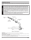
Remote Receiver
Velcro Pad
Velcro
®
Pad
ELECTRICAL WIRING (MILLI-VOLT)
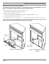
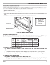
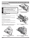
CONNECTING REMOTE RECEIVER
THESE INSTRUCTIONS SUPERSEDE THE SECTION ENTITLED “HEARTH MOUNT” IN THE MILLI-VOLT
HAND-HELD REMOTE INSTRUCTIONS SUPPLIED WITH THE REMOTE.
1. Remove bottom louver door.
2. Connect the remote connectors located in the unit.
3. Stick Velcro
®
pads with self-adhesive backing to bottom of remote receiver and to floor of compartment behind access
panel.
4. Attach remote receiver to firebox with Velcro
®
pads. Control switch must face forward.
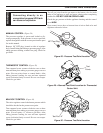
CHECKING SYSTEM OPERATION
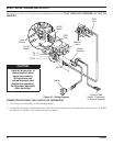
The millivolt system and individual components may be checked with a millivolt meter having a 0-1000 mV range.
Conduct each check shown in chart below by connection meter test leads to terminals as indicated.
A. COMPLETE MILLIVOLT SYSTEM CHECK
(“A” Reading - Thermostat contacts CLOSED - Control Knob “ON” - Main burner should be come
ON)
a. If the reading is more than 100 millivolts and the automatic valve still does not come on, replace the control.
b. If the closed circuit reading (“A” reading) is less than 100 milli-volts, determine cause for low reading, proceed to
Section B below.
B. Thermopile Output Reading Check
(“B” Reading - Thermostat contacts OPEN - Main burner OFF)
1. Check gas pressure to the unit. If gas pressure is within minimum and maximum on data plate, then check pilot
voltage, 325 millivolts minimum. If the minimum milli-volt reading is not obtainable, replace pilot.
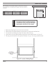
Figure 32 - Installing Remote Receiver
CHECK
TEST
TO
TEST
CONNECT
METER
LEADS TO
TERMINALS
SWITCH OR
THERMOSTAT
CONTACTS
METER
READING
SHOULD BE
A
COMPLETE
SYSTEM
2 & 3 CLOSED CLOSED
B
THERMOPILE
OUTPUT
1 & 2 OPEN OPEN
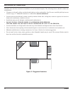
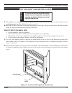
NOTICE
Do not place
remote in
combustion
chamber.