58D56002 17
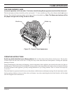
PILOT
HEAT
THERMOSTAT
REMOTE C
ONTROL
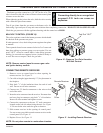
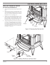
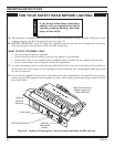
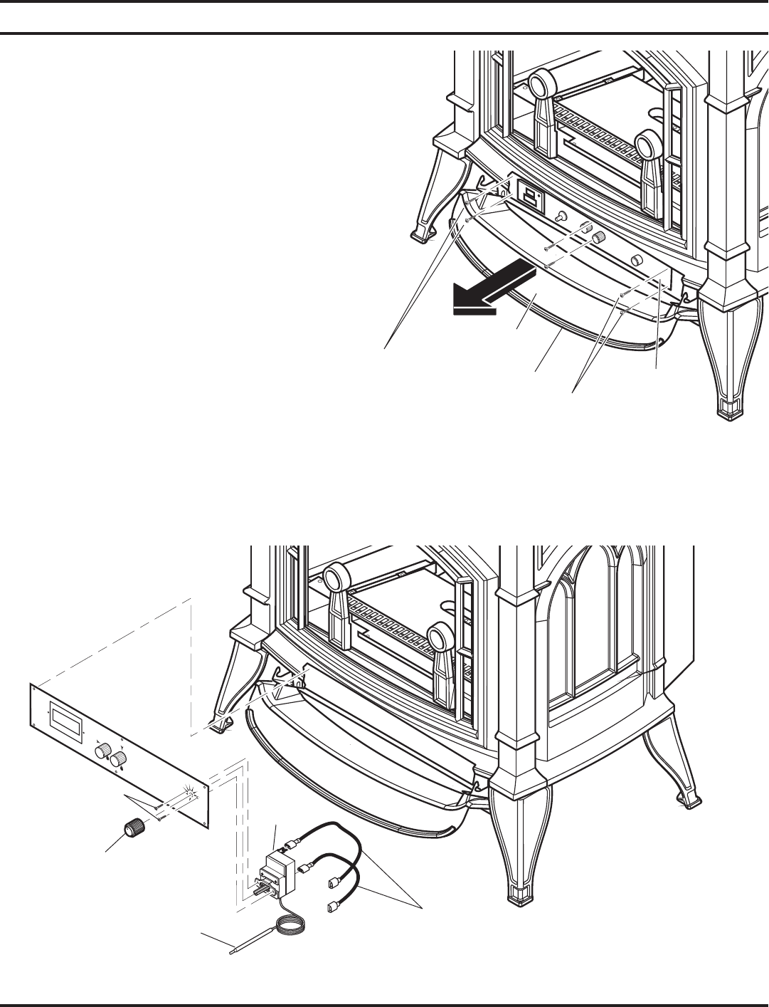
Figure 14 - Installing T-Stat Sensor and Control Knob
T-Stat
Sensor
Wiring
Harnesses
Screws
Knob
INSTALLING THERMOSTAT SENSOR
(OPTION SOLD SEPARATELY)
1. Lift up on ash lip and pivot down to open control
door.
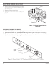
2. Remove the face plate by removing the six (6)
screws holding the faceplate in place. This will
allow you to pull the faceplate away from the
unit about 3" to 4". See Figure 13.
3. Slip the t-stat sensor behind the faceplate. Attach
the t-stat sensor to the faceplate with 2 screws
provided. Make sure the thermo bulb wire is on
the bottom of the t-stat sensor. See Figure 14.
4. Attach wiring harnesses to back of t-stat sensor.
See Figure 14. Attach the other ends of the har-
ness to either TP/TH and TH on control valve or
to existing wiring harness with two (2) 0.250"
male spade terminals for remote t-stat operation.
See Figure 12, page 16.
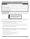
ELECTRICAL WIRING (MILLI-VOLT)
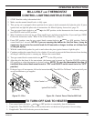
Figure 13 - Removing Face Plate from Unit
Screws
Face Plate
Thermo
Bulb
Screws
Control
Door
Ash
Lip


