


2 3
➤
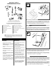
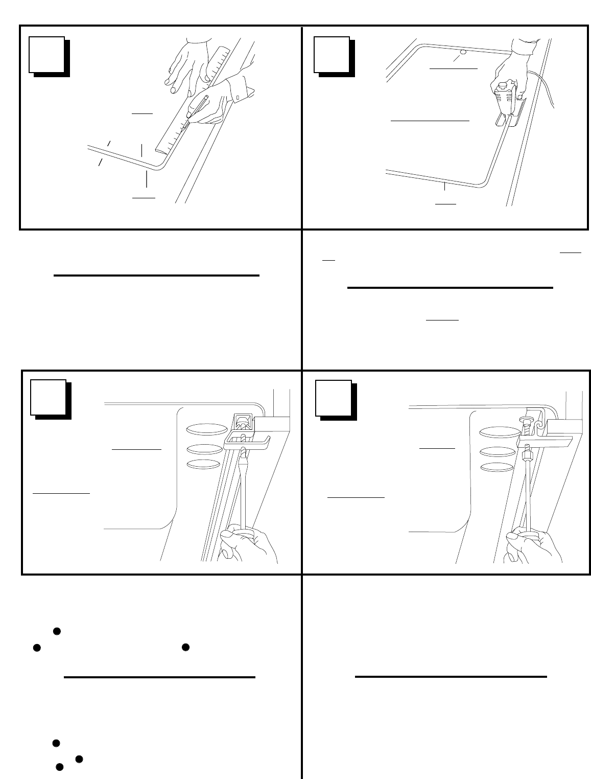
3/8" (9.5mm)DIA. DRILLED HOLE
NOTE: IT IS RECOMMENDED
TO USE A 3/8" (9.5mm) WIDE, 8 TO 10
TEETH-PER-INCH (25.4mm) SABER SAW BLADE.
AGUJERO PERFORADO
DIAMETRO 3/8" (9.5mm)
NOTA: SE RECOMIENDA USAR CUCHILLA
PARA SIERRA CALADORA DE ANCHO 3/8"
(9.5mm), 8 A 10 DIENTES POR PULGADA (25.4mm)
LÍNEA DE
CORTE
CUTOUT
LINE
➤
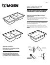
2. Remove sink or template. Draw cutout line 1/4" (6.4mm) INSIDE rim outline. IMPOR-
TANT: 1/4" (6.4mm) measurement is critical. Continue line completely around.
The 1/4" (6.4mm) provides adequate clearance for channel bar.
2. Remueva el fregadero o la plantilla. Dibuje la línea de corte a 1/4" (6.4mm) DENTRO
de la línea de borde. IMPORTANTE: la medida de 1/4" (6.4mm) es crítica. Continúe
la línea completamente al rededor. La medida de 1/4" (6.4mm) provee un espacio libre
adecuado para las grapas “Jiffy” y las barras de canal.
3. It is important that your cutout be EXACT. First drill a 3/8" (9.5 mm) dia. hole for the
saber saw blade on the inside edge of the cutout. Cut sink opening, using the cutout
line as your guide. Brace cutout portion as you complete cut to avoid splintering edge
of hole. Sand edges smooth. Before installing clamps, check fit by placing sink in
cutout. Make sure corners seat properly.
3. Es importante que el corte sea EXACTO. Primero perfore un agujero de 3/8" (9.5 mm)
dentro de la línea de corte para la cuchilla de la sierra caladora. Corte la abertura del
fregadero usando la línea de corte como guía. Asegúre la porción cortada a medida
que avanza para evitar doblamientos a lo largo del borde de la abertura. Lije los bor-
des suavemente. Antes de instalar las grapas, revise el ajuste colocando el fregadero
en la abertura. Asegúrese que las esquinas sientan correctamente.
5
6
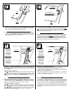
USE SLOTTED
SCREWDRIVER
USE DESARMADOR
PLANO
Clamp Spacing:
For 25" X 22"
(635mm X 559mm)
3 front & back
2 on each side
For 33" X 22"
(838mm X 559mm)
4 front & back
2 on each side
Distancia Entre Grapas:
Para 25" X 22"
(635mm X 559mm)
3 al frente y atrás;
2 en cada lado.
Para 33" X 22"
(838mm X 559mm)
4 al frente y atrás;
2 en cada lado.
6. TO INSTALL "J" CLAMPS IN CHANNEL BAR
With "J" clamps equally spaced, and with one at each end of channel bar,
hand tighten clamps, starting at center and working toward sides. Re-check sink
position on counter top. TIGHTEN ALL CLAMPS AN ADDITIONAL QUARTER TURN.
IMPORTANT - DO NOT OVERTIGHTEN
Clean up all excess caulking and pencil marks from countertop. Use a wet cloth or
sponge and a mild cleanser to remove any grease or fingerprints from sink. Rub gently
with the grain. Installation is now complete.
5. TO INSTALL "U" CLAMPS IN CHANNEL BAR: Side "U" clamps into channel bar from
either open end and/or slots in channel. Position them with claw end under counter top
edge. CAUTION: Improper tightening of clamps could result in improper installation or
cause damage to sink.
Tightening Sequence is as follows:
STEP With "U" clamps equally spaced, and with one at each end of channel bar,
hand tighten clamps, starting at center and working toward sides. STEP
Re-check sink position on counter top. STEP TIGHTEN ALL CLAMPS AN ADDI-
TIONAL QUARTER TURN. IMPORTANT - DO NOT OVERTIGHTEN. Installation is now
complete.
5. INSTALACION DE GRAPAS EN “U” EN BARRAS DE CANAL: Deslice las grapas en
“U” dentro de las barras de canal desde cualquier extremo. Colóquelas con la “uña” de la
grapa bajo el borde de la cubierta. PRECAUCION: El incorrecto apretado de las grapas
puede resultar en una instalación deficiente o causar daños al fregadero.
La Sequencia de Apretado es la Siguiente:
PASO Con las grapas en “U” igualmente espaciadas, y con una en cada extremo de
la barra de canal, apriete a mano las grapas, empezando en el centro y luego hacia los
lados. PASO Revise de nuevo la posición del fregadero en la cubierta.
PASO APRIETE TODAS LAS GRAPAS UN CUARTO DE VUELTA ADICIONAL.
IMPORTANTE - NO APRIETE DEMASIADO. La instalación se ha completado.
6. INSTALACION DE GRAPAS EN “J” EN BARRA DE CANAL
Con las grapas en “J” igualmente espaciadas, y con una en cada extremo de la barra de
canal, apriete a mano las grapas, empezando en el centro y luego hacia los lados.
Revise la posición del fregadero en la cubierta. APRIETE TODAS LAS GRAPAS UN
CUARTO DE VUELTAADICIONAL. IMPORTANTE - NO APRIETE DEMASIADO.
Limpie el exceso del compuesto de calafateo y las marcas de lápiz sobre la cubierta. Use
un paño húmedo o una esponja y un limpiador suave para remover grasa o marcas de
dedos dejadas en el fregadero. Frote suavemente con el grano. La instalación se ha
completado.
USE 3/8"
NUT DRIVER
USE DESARMADOR DE
TUERCAS DE 3/8"
Clamp Spacing:
For 25" X 22"
(635mm X 559mm)
3 front & back
2 on each side
For 33" X 22"
(838mm X 559mm)
4 front & back
2 on each side
Distancia Entre Grapas:
Para 25" X 22"
(635mm X 559mm)
3 al frente y atrás;
2 en cada lado.
Para 33" X 22"
(838mm X 559mm)
4 al frente y atrás;
2 en cada lado.
1
1
3
3
2
2
RIM OUTLINE
1/4"
(6.4mm)
LÍNEA DE
CORTE
CUTOUT
LINE
LÍNEA DE
BORDE
➤
➤
➤
➤