


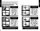


Slightly tighten
set screw.
5/32"
Hex
Not
Included
No sharp edges/burrs on end of pipe.
2
S
1
1
2
2
1
S
English
English
E9
C
D
NO
YES
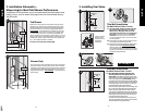
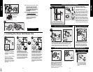
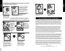
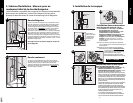
Now you are ready to attach the
handle. Rotate so the notch at the
end of the stem is facing down
towards the drain. Insert the key
stop (C) and the adjustable limit
stop (D) into stop tube as shown.
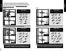
Some models may feature a slip fit installation with no
threaded adapter in the tub spout. For these installa-
tions, slip the tub spout onto pipe pointing up and
slightly tighten the set screw. Rotate tub spout to final
position and fully tighten set screw in place.
4.4
If this is a lever handle that
attaches with the lever handle
adapter (J), attach the plastic
handle adapter (J) to the car-
tridge stem using the 1/2 inch
adapter screw (K). Make sure
the ridges on the back of the
adapter (J) are to the left of the
tab on limit stop (D).
Place the lever (L) on the
lever handle adapter.
L
OR
Slip Fit Tub Spout Installation
For Lever Handles Installed with Plastic Handle Adapter (J)
E8
P
F
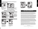
4.6
Place the knob handle
(P) – onto the cartridge -
make sure the indicator
on the knob is pointing
down.
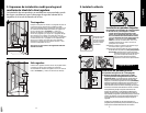
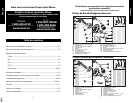
4. Installing Your Moen Tub/Shower Trim
Threaded Tub Spout Installation
If this is a shower only
installation, skip to step 4.4.
IPS (threaded) spouts are
designed to screw onto a pipe
with 1/2 inch male pipe threads.
To determine the proper pipe
length, measure from the inside
elbow shoulder to the wall (y)
and from the threaded adapter
inside of the tub spout to the
base of the tub spout (x), then
add 1/4”. Place thread seal tape
around the pipe threading and a
sealant (plumbers putty or caulk)
around the base of the pipe to
prevent leaking behind the wall.
Tub Spout Installation
(y) + (x) + 1/4” = Pipe Length
To determine the proper pipe length, measure from the inside elbow
shoulder to the wall (y) and from the threaded adapter inside of the
tub spout to the base of the tub spout (x), then add 1/4”.
y
x
1
Thread seal tape
S
2
E
G
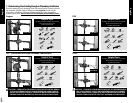
Ensure cartridge
retainer clip is
installed prior to
escutcheon
installation.
G
B
F
3
2
F
Z
1
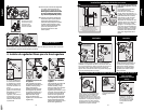
3.5 Once the valve is secured in place,
remove the escutcheon screws
(G) and the plaster ground (E).
Keep the escutcheon screws (G)
for installation of the escutcheon
(F) and discard the plaster
ground (E).
3.6 Place product identification label
(Z) on back of escutcheon
, make
sure wall is clean, place the
escutcheon (F) over the stop tube
(B)
then re-install the screws (G).
A gasket on the back of the
escutcheon provides a seal
against the wall.
3.5
Go To Step 4.1
3.6
4.3A
4.3B
Cartridge Orientation
2
H
1
Thread Seal Tape
Wrap thread seal tape
around the threads of
the shower arm (H) then
screw the arm into the
threaded connection in
the wall.
4.1
If there is a rubber washer
inside the threaded
adapter on the shower-
head, continue to step
4.2A. If there is no rubber
washer, then proceed to
step 4.2B.
2
I
1
A
Thread Seal Tape
3
H
4.2A Plastic Shower Ball
Seal around the shower arm
hole with sealant (caulk) then
slide shower flange (A) over
shower arm (H). Remove any
debris from the shower arm
to ensure proper flow. Then,
simply thread showerhead (I)
onto shower arm (H).
4.2B Metal Shower Ball
Seal around the shower arm
hole with sealant (caulk)
then slide shower flange (A)
over shower arm (H). Wrap
thread seal tape around
threads at bottom of shower
arm (H). Remove any debris
from the shower arm to
ensure proper flow. Thread
showerhead (I) onto shower
arm (H).
OR
4.2A
2
I
1
A
Thread Seal Tape
3
H
4.2B
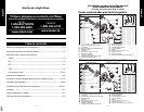
J
D
K
4.5
Other Possible Handle
Type Installations