


12345678
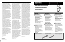
2 Second Flush - 1.0 GPF
3 Second Sensor Arming Time
3 Second Flush - 1.5 GPF
3 Second Sensor Arming Time
12345678
4 Second Flush - 1.6 GPF
4 Second Sensor Arming Time
1 2 3 4 5678
1 Second Flush - 0.5 GPF
3 Second Sensor Arming Time
1 2 3 45678
2.5 Second Flush - 1.28 GPF
4 Second Sensor Arming Time
12345678
7 Second Flush - 3.5 GPF
4 Second Sensor Arming Time
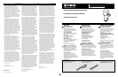
Adjusting Settings
Normal Operation: When new batteries are inserted or AC
power is connected or RESET Button is pushed, the lights on
the Printed Circuit Board (PCB) will blink in the following
sequence: Red, Red (with solenoid clicking), Green, Red and
Red. Green light will stay on. When the user enters the sen-
sor beam's effective range, the Red light will flash one time
on battery-operated flush valves and will stay on on AC-pow-
ered models. If the user stays in the effective range for more
than 4 seconds and steps away, the valve will activate (1)
flush cycle. The flush valve unit will automatically reset for
the next user. When the manual OVERRIDE Button is pushed,
the flushing mechanism will be activated without impacting
the mode of automatic operation. On battery powered mod-
els, the Red indicator light flashes when batteries are low.
Please note: Always push the RESET Button
BEFORE diagnosing any problem and AFTER
taking a corrective action.
Troubleshooting
Battery-Powered & AC-Powered Flush Valves
PROBLEM - FLUSH VALVE WILL NOT FLUSH
POSSIBLE CAUSE TO DIAGNOSE REMEDY
Water does not turned on Check water supply. Turn water on at valve.
Power supply failure Check polarity of batteries (or Power Replace batteries (or Power Adapter).
Adapter voltage) and connections. Push RESET Button.
Batteries are weak Red indicator light flashes, no click. Replace batteries. Push RESET Button.
Sensor distance is too short Stand in front of valve to To adjust sensor distance out, turn
find focal point of sensor beam. adjustment screw clockwise. Push RESET Button.
PC Board does not respond No light, no action. Replace batteries (or Power Adapter).
Replace PCB. Push RESET Button.
Sensor eye does not respond Red indicator light does not blink. Replace batteries (or Power Adapter).
Replace sensor eye and cable. Push RESET Button.
Sensor eye angle adjustment Beam not detecting user. Disassemble control unit, rotate lens up/down
with finger. Push RESET Button.
User time in the sensor range Stand in front of flush valve. The red Stand in sensor range for more than 4 seconds,
is too short indicator light only flashes once. then move away. Push RESET Button.
Solenoid valve is clogged Solenoid is clicking, but water does not flow. Clean solenoid and blow free all by-pass holes.
Replace solenoid. Push RESET Button.
PROBLEM - FLUSH VALVE WILL NOT SHUT OFF
Solenoid coil malfunction Light blinks but no solenoid clicking. Replace batteries (or Power Adapter).
Replace solenoid coil. Push RESET Button.
Solenoid is dirty Solenoid valve is normally closed. Replace solenoid valve. Push RESET Button.
Clicking sound means the solenoid is dirty.
Sensor Operated Flush Valves
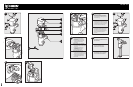
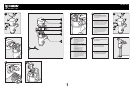
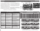
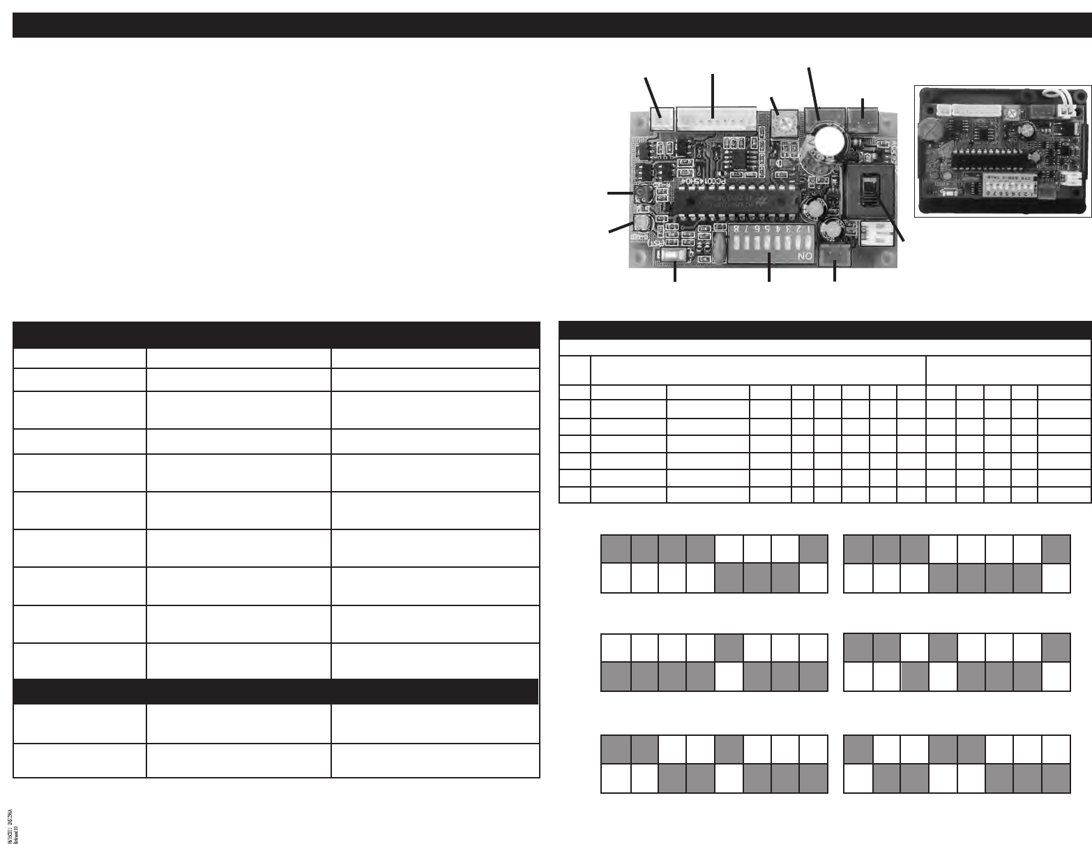
Dip Switch Settings - Push reset button on PC board after any dip switch adjustments
Diagram Flushing Volume (Time) Water Closet or Urinal Sensor Arming Time
# (Sensing Time Required For Flush)
Moen Model Flush Time GPF SW 1 SW 2 SW 3 SW 4 SW 5 SW 6 SW 7 SW 8 Arming Time
1 Urinal Factory pre-set 8315* 1 SEC 0.5 ON ON ON ON OFF OFF OFF ON 3 SEC
2 Urinal Factory pre-set 8312* 8314* 8312R10* 2 SEC 1.0 ON ON ON OFF OFF OFF OFF ON 3 SEC
3
Closet factory pre-set 8311* 2.5 SEC 1.28 OFF OFF OFF OFF ON OFF OFF OFF 4 SEC
4
Urinal Factory pre-set 8312R15* 3 SEC 1.5 ON ON OFF ON OFF OFF OFF ON 3 SEC
5 Closet Factory pre-set 8310* 8313 8310R16* 4 SEC 1.6 ON ON OFF OFF ON OFF OFF OFF 4 SEC
6 Closet Factory pre-set 8310R35* 7 SEC 3.5 ON OFF OFF ON ON OFF OFF OFF 4 SEC
* Includes AC models • Pint and Dual Flush models contain non-adjustable PC boards.
Solenoid pin
connection
Sensor eye cable
pin connector
Sensor distance
adjustment
Battery holder pin
connector (Red)
AC/DC
Switch
Batter holder pin
connector (Red)
Dip switchReset button
Indicator light
(Green)
Indicator light
(Red)
AC power adapter
pin connector (Red)
Worn batteries are the leading cause of malfunctions.
ON
OFF
ON
OFF
ON
OFF
All flush valves are intended for use with matching flow rates as specified by the fixture manufacturer
Note: Pint and Dual Flush models
contain non-adjustable PC boards.
12345678