


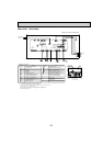
29
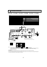
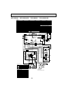
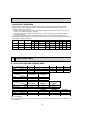
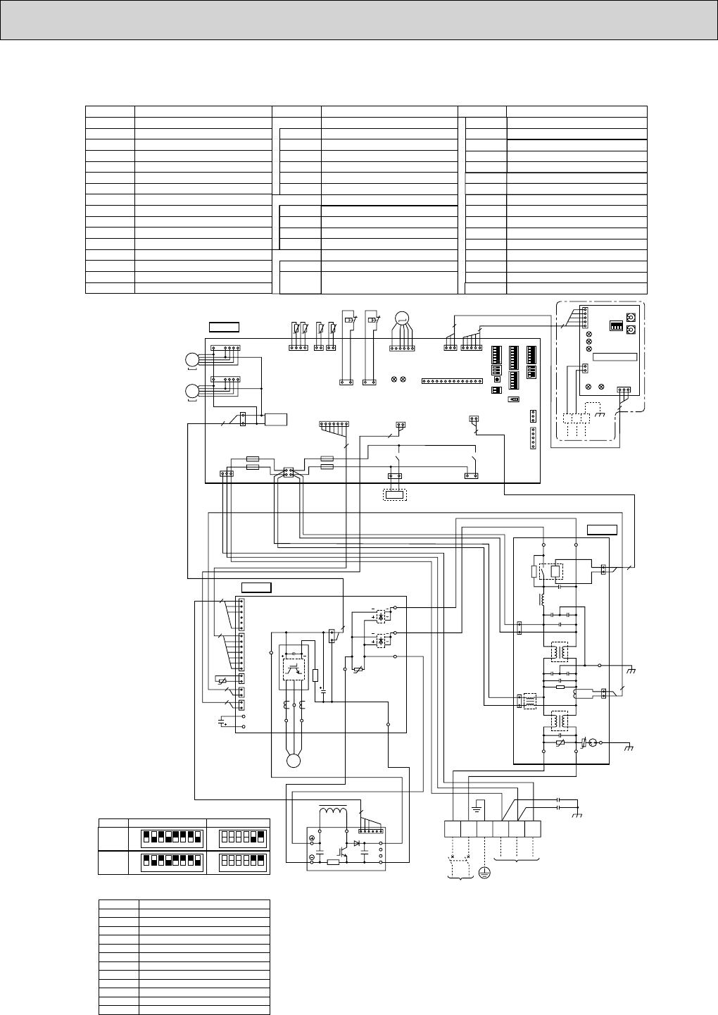
PUZ-A42NHA3 PUZ-A42NHA3-BS PUY-A42NHA3 PUY-A42NHA3-BS
TB1
MC
MF1,MF2
21S4
63H
63L
TH3
TH4
TH6
TH7
TH8
LEV-A
DCL
Terminal Block<Power Supply, Indoor/Outdoor >
Motor for Compressor
Fan Motor
Solenoid Valve (Four-Way Valve)
High Pressure Switch
Low Pressure Switch
Thermistor<Outdoor Pipe>
Thermistor<Discharge>
Thermistor<Outdoor 2-Phase Pipe>
Thermistor<Outdoor>
Thermistor<Heatsink>
Electronic Expansion Valve
Reactor
ACTM
Active Filter Module
CB
Main Smoothing Capacitor
Power Circuit Board
Connection Terminal<U/V/W-Phase>
Diode Bridge
P.B.
TABU/V/W
Noise Filter Circuit Board
Connection Lead<L1-Phase>
Connection Terminal<Ground>
N.F.
LI/LO
Connection Lead<L2-Phase>
NI/NO
52C Relay
52C
EI, E2
Controller Circuit Board
Switch<Pump Down>
Connector<Emergency Operation>
SWP
CN31
C.B.
DS2, DS3
Power Module
IPM
SYMBOL
[LEGEND]
NAME SYMBOL NAME SYMBOL NAME
Connection Terminal<L1/L2-Phase>
TABS/T
Connection Terminal<DC Voltage>
TABP1/P2/P
Connection Terminal<DC Voltage>
TABN1/N2/N
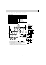
Switch<Function Setup>
SW8
Switch
SW9
Fuse<
T6.3AL250V>
Switch<
Forced Defrost, Defect History Record
Reset, Refrigerant Address>
Switch<Function Switch>
Switch<Model Select>
F1~F4
SW1
SW5
SW6
Switch<Function Setup>
SW7
LED1,LED2
LED<Operation Inspection Indicators>
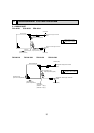
CNM
CNMNT
CNVMNT
CNDM
Connector<A-Control Service Inspection Kit>
Connector<Connected to Optional M-NET Adapter Board>
Connector<Connected to Optional M-NET Adapter Board>
Connector< Connected for Option (Contact Input)>
X51,X52
Relay
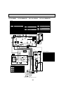
SYMBOL
M-NET ADAPTER
NAME
TB7
CN5
CND
CN2M
SW1
SW11
SW12
LED1
LED2
LED3
LED4
LED5
Terminal Block<M-net connection>
Connector<Transmission>
Connector<Power Supply>
Connector<M-NET communication>
Switch<Status of communication>
Switch<Address setting : 1s digit>
Switch<Address setting : 10s digit>
LED<Power Supply : DC5V>
LED<Connection to Outdoor Unit>
LED<Transmission : Sending>
LED<Transmission : Recelving>
LED<Power Supply : DC12V>
+Use copper supply wires.
CY1, CY2 Capacitor
Switch<Test Operation>
SW4
123456
OFF
ON
PUZ-A42N
MODEL SW6
+1 MODEL SELECT
SW5
-
5.6
123456
OFF
ON
PUY-A42N
78
78
123456
OFF
ON
123456
OFF
ON
+2
+2. SW5-1 to 4 : Function switch
Connector<Connection for Option>
SS
CN51
Connector< Connected for Option (Signal output)>
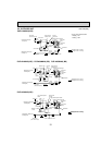
C. B.
CNF1
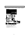
(WHT)
MF1
MS
3~
7
1
CNF2
(WHT)
MF2
MS
3~
7
1
TRANS
CNDC
(PNK)
3
2
1
TH7/6
(RED)
63L
(RED)
TH3
(WHT)
TH4
(WHT)
TH7TH6 TH3 TH4
412121
31
t° t° t° t°
63L
63H
(YLW)
31
63H
LEV-A
(WHT)
LEV-A
M
LED1
LED2
61
CNVMNT
(WHT)
31
CNDM
(WHT)
CN51
(WHT)
WHT
WHT
WHT
WHT
3151
CNMNT
(WHT)
CNM
(WHT)
51
3
5
SW7
SW6SW1
SW9
CN31
1
+1+1
SW5SW8SW4SWP
14
X51
CNS
(WHT)
CNAC
(WHT)
SS
(WHT)
21S4
(GRN)
X52
F1
F2
F4
F3
21
43
21S4
31
13 13
CN4
(WHT)
12
2
CN52C
(RED)
2
2
1
CN2
(WHT)
71
7
CN5
(WHT)
31
LED2
SW1
SW11
SW12
LED3
LED4
TB7
LED1
LED5
2
1
CND
(WHT)
CN2M
(WHT)
M-NET ADAPTER
M-NET
ABS
When M-NET adapter is connected
5
3
5
1
+2 PUZ only
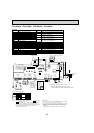
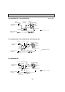
P. B.
2
1
3
7
1
1
2
1
2
1
2
7
6
2
2
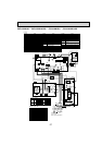
CNDC
(PNK)
DS2
DS3
TABN
TABP
IPM
U
TABP2
TABV
TABW
TABN2
TABN1
TABS
TABP1
TABT
TABU
M
3~
U
V
W
MC
CB
CN2
(WHT)
4
1
CNAF
(WHT)
CN4
(WHT)
CN5
(RED)
CN3
(WHT)
TH8
t°
DCL
ACTM
L1
LO
52C
NO
LI NI
CN5
(RED)
L2
N2
Io
N1
P
4
16
CNAC2
(RED)
CN52C
(BLK)
CNAC1
(WHT)
2
2
1
3
E2
EI
U
U
1
2
1
2
3
1
N. F.
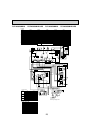
POWER SUPPLY
208 / 230V 60Hz
INDOOR
UNIT
TB1
S1 S2 S3
RED
BLU
BLU
BLK
GRN
ORN
YLW
BRN
L1 L2 GR
WHT
REDRED
RED
RED
BLU
WHT
RED
BLK
BLK
BLK
RED
WHT
CY2
CY1