


30
DISASSEMBLY PROCEDURE
OPERATING PROCEDURE PHOTOS & ILLUSTRATIONS
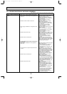
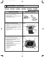
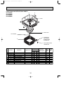
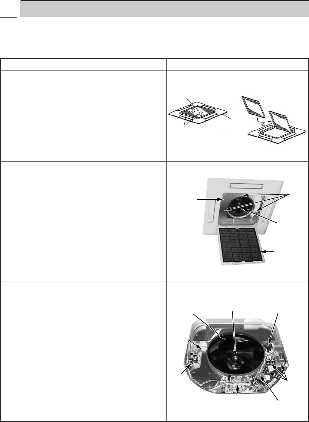
1. Removing the air intake grille
(1) Slide the knob of air intake grille to the direction of the
arrow 1 to open the air intake grille.
(2) Remove the string hook from the panel to prevent the
grille from dropping.
(3) Slide the shaft in the hinge to the direction of the arrow2
and remove the air intake grille.
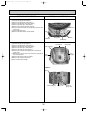
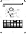
3. Removing the electrical box
(1) Disconnect the lead wire of the vane motor from the clamp,
and disconnect the white connector (10P).
(2) Remove the room temperature thermistor with the holder.
(3) Remove the bell mouth.(See photo 1)
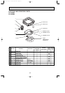
(4) Disconnect the relay connector in the electrical box.
Red (3P) for fan motor
Disconnect the connector on the indoor controller board.
White (2P) for pipe temperature detecting thermistor
Blue (3P) for drain pump
White (3P) for drain sensor
(5) Remove the 3 screws from the electrical box, loosen
another 2 screws to remove the box.
<Electrical parts in the electrical box>
Indoor controller board
Power board
Terminal block
Capacitor
Be careful on removing heavy parts.
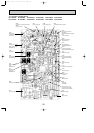
Photo 2
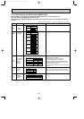
Figure 1
Air intake grille
Grille
Nut
Air intake grille knob
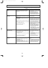
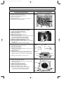
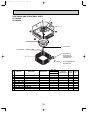
2. Removing the room temperature thermistor
(1) Remove the screw(✕1) in the room temperature thermistor
holder to remove the holder and the room temperature
thermistor.
(2) Remove the 1 screw from the bell mouth, and unscrew the
other 2 screws (fix to the oval hole which has a different
diameter) to remove the bell mouth.
(3) Hold the holder claw, and remove the room temperature
thermistor and holder.
(4) Disconnect the connector (CN20:red) on the indoor control
board.
Bell mouth
Indoor controller board
Connector
Terminal
block
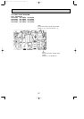
Photo 1
Screws
Room
temperature
thermistor
Air intake grille
Electrical
box
Power
board
Turbo fan
Capacitor
11
PLA-A12AA PLA-A18AA PLA-A24AA PLA-A30AA PLA-A36AA PLA-A42AA
PLA-A12AA1 PLA-A18AA1 PLA-A24AA1 PLA-A30AA1 PLA-A36AA1 PLA-A42AA1
OC370B--1.qxp 07.6.20 2:42 PM Page 30