


22
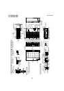
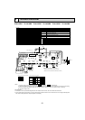
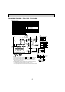
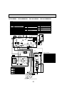
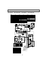
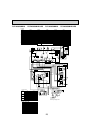
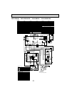
PKA-A12HA PKA-A18HA PKA-A12HAL PKA-A18HAL
Symbol
Name
Symbol
Name
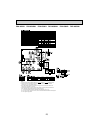
I.B Indoor controller board
FUSE FUSE(T3.15AL250V)
ZNR01,02
Varistor
DSA Surge absorber
CN2L Connector (LOSSNAY)
CN30 Connector (LLC)
CN152 Connector (Back-up heating)
CN90 Connector (Remote operation adapter)
Connector (Emergency operation)
CN32 Connector ( Remote switch)
CN41 Connector (HA terminal-A)
CN51 Connector (Centrally control)
LED1 Power supply (I.B)
LED2 Power supply (R.B)
LED3 Transmission (Indoor-outdoor)
SW1 Switch (Model selection) +See table 1
SW2
SWE
Switch (Capacity code) +See table 2
[Explanation of symbols]
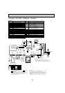
MS Fan motor
W.B Pcb for wireless remote controller
Switch board
SWE2 Emergency operation
M Vane motor
LED1 LED (Operation indication: Green)
REC1 Receiving unit
LED2 LED (Preparation for heating: Orange)
TB2 Terminal block(Indoor unit Power (option))
TB4 Terminal block (Indoor/outdoor connecting line)
TB5 Terminal block (Remote controller transmission line)
TH1 Room temp. Thermistor
Pipe temp. Thermistor/liquid
Cond./eva. temp. Thermistor
(32°F/15ΚΩ, 77°F/5.4ΚΩ Detect)
(32°F/15ΚΩ, 77°F/5.4ΚΩ Detect)
(32°F/15ΚΩ, 77°F/5.4ΚΩ Detect)
TH2
TH5
S.W
R.B
Wired remote controller
TB6
Terminal block (Remote controller transmission line)
Notes:
1.SymboIs used in wiring diagram above are, : Connector, : Terminal (block).
2.Indoor and outdoor connecting wires have poIarities, make sure to match terminal
numbers (S1, S2, S3)for correct wirings.
3.Since the outdoor side electric wiring may change, be sure to check the outdoor unit
electric wiring diagram for servicing.
4.This diagram shows the wiring of indoor and outdoor connecting wires.(specification of
230V), adopting superimposed system for power and signal.
+
1: If indoor and outdoor units have separate power supplies, refer to Fig 1.
+
2: For power supply system of this unit, refer to the caution label located near this diagram.
+
3: Use copper supply wires.
TO OUTDOOR
UNIT
5
3
1
3
1
CN01
(BLK)
ORN
YLW
BLU
RED
GRN
/
YLW
I.B
+1(Fig. 1)
I.B
POWER SUPPLY
208/230V 60Hz
L1
L2
GR
ORN
ORN
YLW
BRN
TB4
TB2
S1
S2
S3
INDOOR/OUTDOOR
COMMUNICATION
CN3C(BLU)
Refer to
tables
1and 2
CN90
(WHT)
CN2L
(RED)
CN151
(WHT)
CN20
(RED)
CN44
(WHT)
CN4F
(WHT)
CN22
(BLU)
CN41
(WHT)
CN51
(WHT)
CN32
(WHT)
ZNR01
ZNR02
CNMF
(WHT)
S.W
SWE
R.B
CNP(BLU)
CN3C
(BLU)
LDSWE(A
)
(BLU)
LDSWE(B) SWE2
CN01
(BLK)
T11 DB1
X1
U
U
FUSE
I.B
1
1
11 1 54
11
1
2
141425
TH1 TH2 TH5
2
1139
CN152
(WHT)
CN30
(BLK)
11310
3
3
3
2
2
1
2
1
1
1
5
6
DSA
M
t
○
t
○
t
○
MS
3~
TB4
<+3>
TB5
S1
S2
S3
BLU
BLU
ORN
ORN
ORN
BRN
LED1
LED3
LED2
For PKA-A.HA
TB6
ON
OFF
TO
OUTDOOR
UNIT
YLWYLW
BLK
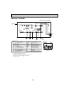
<Table 1>
SW1
(MODEL SELECTION)
SETTING
SETTING
ON
OFF
12345
<Table 2>
SW2(CAPACITY CODE)
MODELS
A12
ON
OFF
12345
ON
OFF
12345
A18
W.B
CNRU
(WHT)
LD101(B)
REC1
LED1
LED2
6
RU