30
10
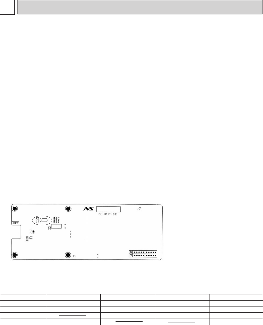
The P.C.board has the print “J1” and “J2”. Jumper wires are mounted to each “J1” and “J2”. Cut “J1” and “J2” according to
the number of indoor unit as shown in Table 1.
After modification, push the RESET button near the MIN-button on the remote controller.
NOTE : For remodeling, take out the
batteries first.
After finish remodeling, put
back the batteries then
push the RESET-button.
Table.1
Note : At power supply failure or installation, indoor unit deletes the memory about remote controller. When the
power supply is turned on and indoor unit receives the first signals from the remote controller, the remote
controller number is designated as the indoor unit number. Therefore at and after the second time indoor
unit accepts the remote controller of the initial setting number.
At setting-error, turn the power supply off to cancel the individual operation, and then turn the power supply
on to restart the setting.
MS09NW, MS12NN, MS15NN, MS17NN
3. P.C. BOARD MODIFICATION FOR INDIVIDUAL OPERATION
A maximum of 4 indoor units with wireless remote controllers can be used in a room.
In this case, to operate each indoor unit individually by each remote controller, P.C. boards of remote controller must be
modified according to the indoor unit number.
How to modify the remote controller P.C. board
Remove batteries before modification.
The board has a print as shown below :
1. AUTO RESTART FUNCTION
When the indoor unit is operated with the remote controller, the signals of the operation mode, the set temperature, and the
fan speed are sent from the indoor electronic control P.C.board and memorized in the auto restart assembly.
When the main power is turned off and then turned back on, the unit restarts automatically in the memorized set conditions
approximately after 3 seconds.
NOTE:
a) When the unit operation is stopped with the Emergency Operation Switch, the unit does not restart after the power is
restored, since the signal of “Operation Stop” is memorized in the auto restart assy.
b) Operation details may not be memorized in case the signal is transmitted by the remote controller to turn the main
power OFF within 10 seconds after the power ON. .
c) When the unit operation is stopped with the remote controller before power failure, the unit does not restart until the
OPERATE/STOP (ON/OFF) button on the remote controller is pressed.
2. TIMER SHORT MODE
For service, set time can be shortened by short circuit of JPG and JPS on the electronics control P.C. board.
The time will be shortened as follows.
3-minute delay : 3-minute ➔ 3-second.
AUTO START : 1 hour ➔ 1-minutes
AUTO STOP : 1 hour ➔ 1-minutes
Short the connector during the timer mode.
}
SERVICE FUNCTIONS
No.1 unit
No.2 unit
No.3 unit
No.4 unit
1 unit operation
No modification
2 unit operation
Same as at left
Cut J1
3 unit operation
Same as at left
Same as at left
Cut J2
4 unit operation
Same as at left
Same as at left
Same as at left
Cut both J1 and J2
OB192--1.qxp 23/6/97 11:47 PM Page 30


