39
12
OPERATING PROCEDURE PHOTOS
1. Removing the front panel
(1) Remove the screws caps of the front panel.
Remove the screws.
(2) Pull the panel down to your side slightly and unhook the
catches at the top.
2. Removing the electronic control P.C. board and the
display P.C. board.
(1) Remove the front panel. (Refer to 1)
(2) Remove the screw of the electrical cover.
Remove the electrical cover.
(3) Disconnect the room temperature thermistor and the con-
nector from the indoor coil thermistor.
(4) Remove the terminal cover.
Remove the screw of the terminal block.
(5) Disconnect all the connectors on the electronic control P.C.
board.
(6) Disconnect the white lead wire and the black lead wire from
52C relay.
(7) Remove the electronic control P.C. board and the display
P.C. board.
12-1 MS09NW
INDOOR UNIT
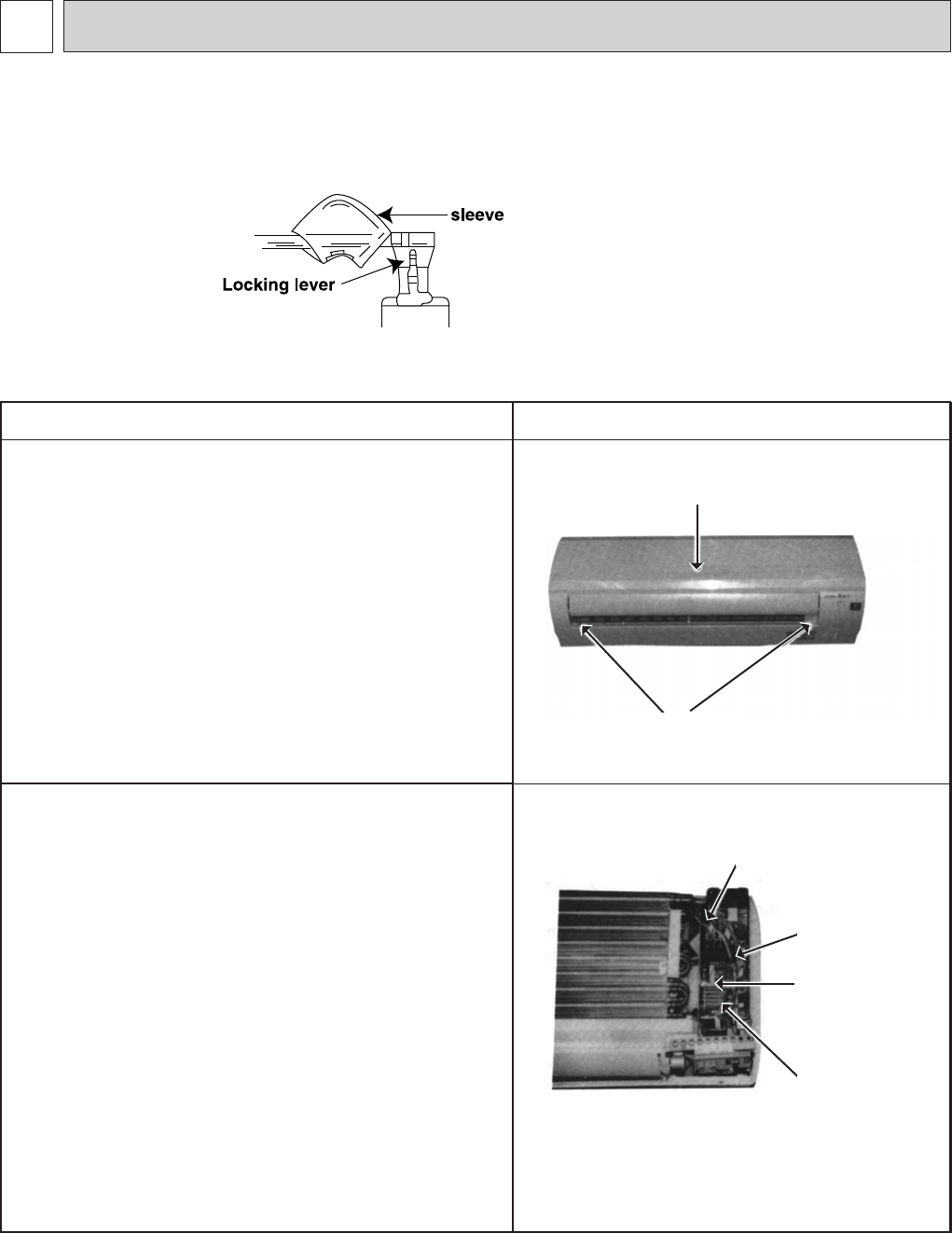
NOTE:
w on the wiring diagram shows the terminals with a lock mechanism, so it
cannot be removed when you pull the lead wire. Be sure to pull the wire by
pushing the locking lever (projected part) of the terminal with a finger.
11
Slide the sleeve.
22
Pull the wire while pushing
the locking lever.
Photo 1
Photo 2
Screw
Indoor electronic
control P.C.
board
Terminal block
cover
Terminal block
cover screw
Room temperature
thermistor connector
Front panel
DISASSEMBLY INSTRUCTIONS
OB192--2.qxp 23/6/97 11:52 PM Page 39


