


7
S1
S2
S3
S1
S2
S3
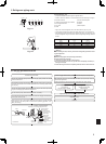
6. Electrical work
7. Maintenance
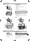
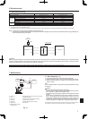
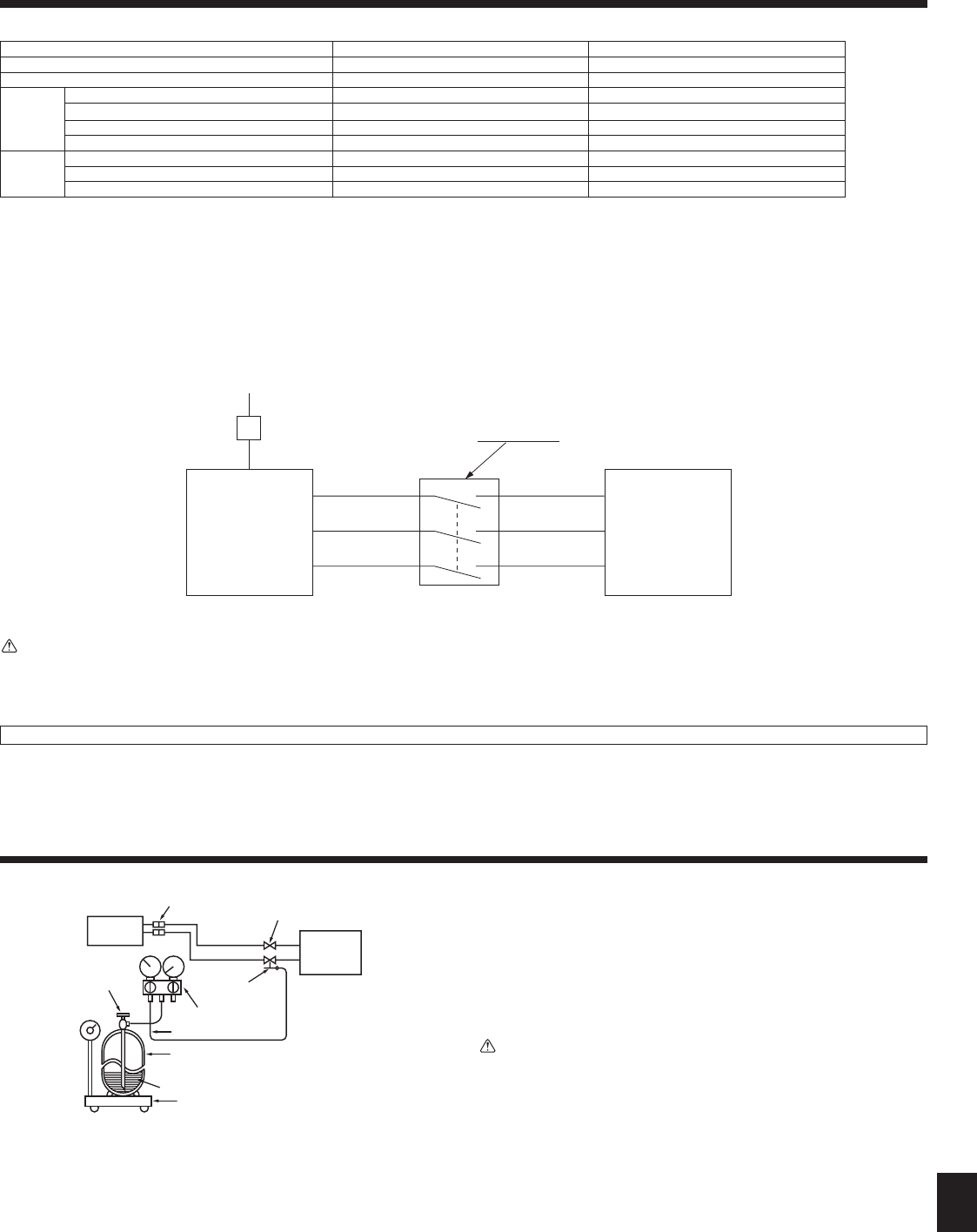
7.1. Gas charge (Fig. 7-1)
1. Connect gas cylinder to the service port of stop valve (3-way).
2.
Execute air purge of the pipe (or hose) coming from refrigerant gas cylinder.
3. Replenish specified amount of refrigerant, while running the air condi-
tioner for cooling.
Note:
In case of adding refrigerant, comply with the quantity specied for the refrig-
erating cycle.
Caution:
• Do not discharge the refrigerant into the atmosphere.
Take care not to discharge refrigerant into the atmosphere during installa-
tion, reinstallation, or repairs to the refrigerant circuit.
• For additional charging, charge the refrigerant from liquid phase of the gas
cylinder.
If the refrigerant is charged from the gas phase, composition change may
occur in the refrigerant inside the cylinder and the outdoor unit. In this
case, ability of the refrigerating cycle decreases or normal operation can
be impossible. However, charging the liquid refrigerant all at once may
cause the compressor to be locked. Thus, charge the refrigerant slowly.
To maintain the high pressure of the gas cylinder, warm the gas cylinder with warm
water(under40°C)duringcoldseason.Butneverusenakedreorsteam.
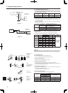
6.2. Field electrical wiring
Outdoor unit model SUZ-KA25/KA35 SUZ-KA50/KA60/KA71
Outdoor unit power supply ~/N (single), 50 Hz, 230 V ~/N (single), 50 Hz, 230 V
Outdoor unit input capacity Main switch (Breaker) *1 10 A 20 A
Wiring
Wire No. ×
size (mm
2
)
Outdoor unit power supply 2 × Min. 1.5 2 × Min. 2.5
Outdoor unit power supply earth 1 × Min. 1.5 1 × Min. 2.5
Indoor unit-Outdoor unit 3 × 1.5 (Polar) 3 × 1.5 (Polar)
Indoor unit-Outdoor unit earth 1 × Min. 1.5 1 × Min. 1.5
Circuit
rating
Outdoor unit L-N *2 AC 230 V AC 230 V
Indoor unit-Outdoor unit S1-S2 *2 AC 230 V AC 230 V
Indoor unit-Outdoor unit S2-S3 *2 DC 12 V ~ DC 24 V DC 12 V ~ DC 24 V
*1. A breaker with at least 3 mm contact separation in each poles shall be provided. Use earth leakage breaker (NV).
*2.TheguresareNOTalwaysagainsttheground.
S3 terminal has DC 24 V against S2 terminal. However between S3 and S1, these terminals are NOT electrically insulated by the transformer or other device.
Notes: 1. Wiring size must comply with the applicable local and national code.
2. Power supply cords and Indoor/Outdoor unit connecting cords shall not be lighter than polychloroprene sheathed exible cord. (Design 60245 IEC 57)
3. Install an earth longer than other cables.
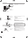
Outdoor Unit
3 poles isolator
230 V
Single phase
Isolator
Indoor Unit
Warning:
There is high voltage potential on the S3 terminal caused by electrical circuit design that has no electrical insulation between power line and communication
signal line. Therefore, please turn off the main power supply when servicing. And do not touch the S1, S2, S3 terminals when the power is energized. If isolator
should be used between indoor unit and outdoor unit, please use 3-poles type.
A Indoor unit H Refrigerant gas cylinder for R410A with siphon
B Union I Refrigerant (liquid)
C Liquid pipe J Electronic scale for refrigerant charging
D Gas pipe K Charge hose (for R410A)
E Stop valve L Gauge manifold valve (for R410A)
F Outdoor unit M Service port
G Refrigerant gas cylinder
operating valve
Fig. 7-1
Neversplicethepowercableortheindoor-outdoorconnectioncable,otherwiseitmayresultinasmoke,areorcommunicationfailure.