4G9 ENGINE (E-W) -
Cylinder Head and Valves
11A-9-11
PWEE9502-C
E
July 1997MitsubishiMotors Corporation
Revised
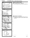
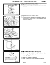
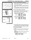
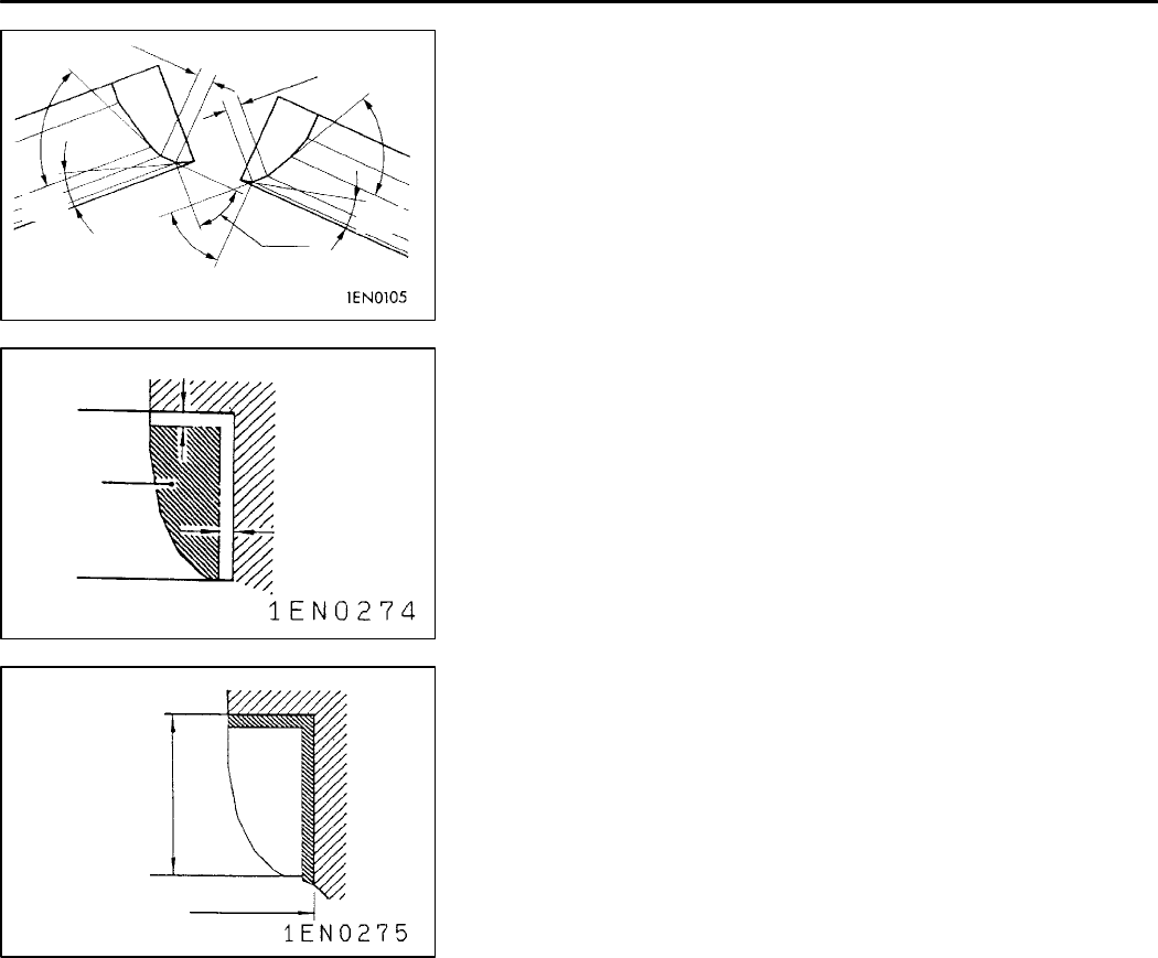
VALVE SEAT RECONDITIONING PROCEDURE
(1) Before correcting the valve seat, check the clearance
between the valve guide and valve. If necessary, replace
the valve and/or valve guide.
(2) Using the appropriate special tool or seat grinder, correct
the valve seat to achieve the specified seat width and
angle.
(3) After correcting the valve seat, lap the valve and valve
seat using lapping compound. Then, check the valve
stem projection (refer to VALVE SEAT in INSPECTION).
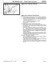
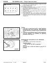
VALVE SEAT REPLACEMENT PROCEDURE
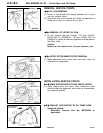
(1) Cut the valve seat to be replaced from the inside to thin
the wall thickness. Then, remove the valve seat.
(2) Rebore the valve seat hole in the cylinder head to a
selected oversize valve seat diameter.
Intake valve seat hole diameter
0.3 O.S. <SOHC>: 31.80 - 31.83 mm
<DOHC>: 34.30 - 34.33 mm
0.6 O.S. <SOHC>: 32.10 - 32.13 mm
<DOHC>: 34.60 - 34.63 mm
Exhaust valve seat hole diameter
0.3 O.S. <SOHC>: 29.30 - 29.32 mm
<DOHC>: 30.80 - 30.83 mm
0.6 O.S. <SOHC>: 29.60 - 29.62 mm
<DOHC>: 31.10 - 31.13 mm
(3) Before fitting the valve seat, either heat the cylinder head
up to approximately 250
_
C or cool the valve seat in liquid
nitrogen, to prevent the cylinder head bore from galling.
(4) Correct the valve seat to the specified width and angle.
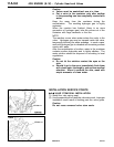
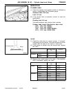
VALVE GUIDE REPLACEMENT
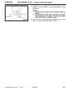
(1) Force the valve guide out toward the cylinder block using
a press.
(2) Machine the valve guide hole in the cylinder head to
the size of the oversize valve guide to be installed.
Caution
Do not use the valve guide of the same size as the
removed one.
Valve guide hole diameters in cylinder head
0.05 O.S.: 11.05 - 11.07 mm
0.25 O.S.: 11.25 - 11.27 mm
0.50 O.S.: 11.50 - 11.52 mm
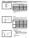
0.9 - 1.3 mm
0.9 - 1.3 mm
65
_
65
_
44
_
44
_
15
_
15
_
0.5 - 1.0 mm
Cut away
0.5 - 1.0 mm
Valve seat
height
Oversize valve seat
hole diameter


