


19
8-2. PLA-A·BA
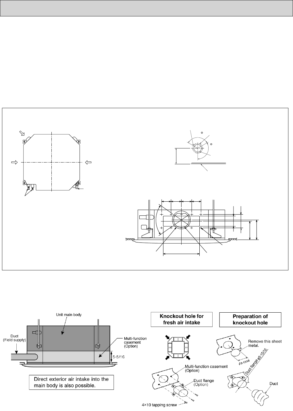
8-2-1 FRESH AIR INTAKE AND BRANCH DUCT
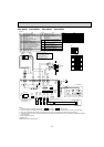
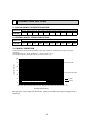
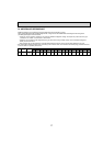
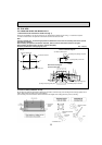
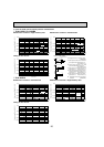
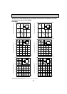
1. Branch duct hole and fresh air intake hole (Fig. 1)
At the time of installation, use the duct holes (cut out) located at the positions shown in Fig.1, as and when required.
• A fresh air intake hole for the optional multi function casement can also be made.
Note:
The figure marked with * in the drawing represent the dimensions of the main unit excluding those of the optional
multi function casement.
When installing the optional multi function casement, add 5-5/16 to the dimensions marked on the figure.
When installing the branch ducts, be sure to insulate adequately.
Otherwise condensation and dripping may occur.
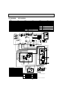
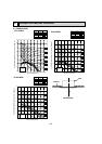
Branch duct hole
14-:1/8(:2.8) burring hole
Indoor unit
:5-29/32(:150) cut out hole
Fresh air intake hole
:6-7/8(:175) burring hole pitch
Drain pipe
Fresh air intake hole diagram
Unit : inch(mm)
Refrigerant pipe
3-:1/8(:2.8) burring hole
Branch duct hole diagram
(view from either side)
:4-29/32(:125) burring hole pitch
3-:15/16(:100) cut out hole
Ceiling
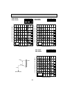
6-7/32
(*158)
120
120
13-25/32(350)
3-17/32
(90)
3-15/16
(100)
3-15/16
(90)
3-17/32
(90)
70
3-15/16(100)
5-1/8(130)
*6-3/32(155)
*6-9/16(167)
[Fig. 1]
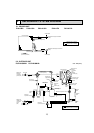
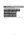
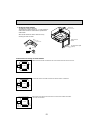
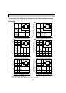
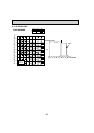
2. Fresh air intake (Installation at site)
By mounting the optional multi-function casement to the indoor unit main body, and mounting the duct flange (option) onto it
further, fresh exterior air intake can be accomplished.
(The mounting of the multi-function casement increases the height of the ceiling plenum by 5-5/16 (135mm).)