


Specications are subject to change without notice.
© 2014 Mitsubishi Electric US, Inc.
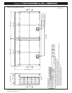
Modules 1 & 2: PUHY-P120YKMU-A (-BS) – DIMENSIONS
(5-17/32) (3-1/16)
(5-29/32) (3-23/32)
(2-1/16)
(1-11/32)
(1-3/8)
(7/8)
(2-15/32)
(1-3/4)
(2-9/16)
(1/2)
(1/2)
(1-1/8)
(1-1/8)
(3/8)
(1/2)
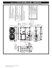
Fan box
ø12.7 Brazed
ø12.7
ø28.58 Brazed
ø28.58
ø9.52 Brazed
Note1.Please refer to the engineering manual for information
regarding necessary spacing around the unit and
foundation work. Outdoor unit must be mounted at least
12" off the ground or 12" above the highest average snow
depth, whichever is greater.
2.At brazing of pipes, wrap the refrigerant service valve
with wet cloth and keep the temperature of
refrigerant service valve under 120°C(248°F).
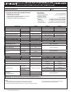
Refrigerant pipe Service valve
Diameter
Model
Connecting pipe specifications
(ø12.7 Brazed)
PUHY-P144YKMU
PUHY-P120YKMU
Gas GasLiquidLiquid
(26-13/16)
(3-5/32)
(3-5/32)
(2-25/32)
(11-15/16)
(4-25/32)
(5-23/32)
(3-5/16)
(1-3/16)
(1-3/16)
(3-23/32)
(5-31/32)
(7-23/32)
(8-9/16)
(3-17/32) (3-1/16)
(23-5/8)
(25/32)
(25/32)
(13/16) (13/16)
(2-1/4)
(2-1/4)
2
1
4
7
3
2X2-80(3-5/32)X35(1-13/32) Oval hole
<Sling hole>
5
6
Discharge air
Intake
air
Intake
air
Transformer box
Service
panel
Intake
air
2X3-14(9/16)X20(13/16) Oval hole
(Mounting pitch)
(Mounting pitch)
(Mounting pitch)
Control box
Refrigerant service valve
<liquid>
Refrigerant service valve
<gas>
Service panel
2X7-ø4.6(3/16) Hole
(Make hole at the plastic fan guard
for snow hood attachment)
<Snow hood attachment hole>
Refrigerant service
valve <gas>
Refrigerant service
valve <liquid>
(6-25/32)
(8-25/32)
ø65 Knockout hole
ø34 Knockout hole
For transmission cables
ø52 Knockout hole
For pipes
Bottom through hole
150 × 94 Knockout hole
140 × 77 Knockout hole
Front through hole
NO.
Usage
For wires
Front through hole
Front through hole
Bottom through hole
Bottom through hole
Front through hole
ø62.7 or ø34.5 Knockout hole
ø43.7 or ø22.2 Knockout hole
Specifications
*1 Expand the on-site piping and connect to the refrigerant service valve piping.
*2 Use the pipe joint(field supply) and connect to the refrigerant service valve piping.
*3 Indicates dimensions and connection specifications in the case the unit is
used in combination with other outdoor units.
*4 Furthest piping length (OU from IU) 40m(131ft)
*1 *3 *4
*2
*1
*2
58(2-5/16)
75(2-31/32)
541(21-5/16)
217
172
196
151
121
303
1347(53-1/16)
1650(64-31/32)
1750(68-29/32)
19.5
831(32-23/32)
831(32-23/32)
19.5
60070
(740)(29-5/32)
29.529.5
562(22-5/32)
740(29-5/32)
7789
80
795(31-5/16)
795(31-5/16)
80
681
140(5-17/32)
49(1-15/16)
54(2-5/32)
57
20
586(23-3/32)
57
20
223
145
590(23-1/4)
83(3-9/32)
150(5-29/32)
561(22-3/32)
516(20-11/32)
8494
Front view
Top view
Left side view
Bottom view
PUHY-P120,144YKMU-A(-BS)
Unit : mm(in.)
1
2
3
4
5
6
7
>
=