


10
6
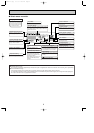
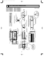
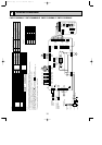
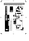
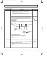
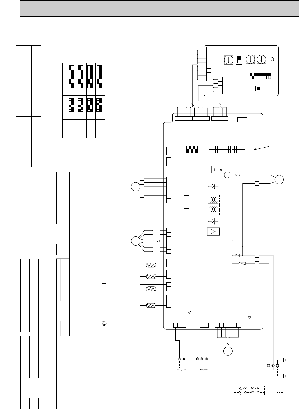
WIRING DIAGRAM
Note
1.At servicing for outdoor unit, always follow the wiring diagram of outdoor unit.
2.In case of using MA-Remote controller, please connect to TB15. (Remote controller wire is non-polar.)
3.In case of using M-NET, please connect to TB5. (Transmission wire is non-polar.)
4.Symbol [S] of TB5 is the shield wire connection.
5.Symbols used in wiring diagram above are, : terminal block, :connecter.
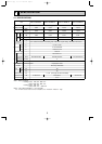
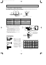
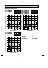
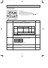
6.The setting of the SW2, SW3 dip switches differs in the capacity for the detail, refer to the fig : w1.
7.Please set the switch SW5 according to the power supply voltage.
CN51
CN52
SW2
SW3
SW4
A.B Address board
SW1
SW5
SW11
SW12
Mode selection
Voltage selection
Address setting 1st digit
Address setting 2nd digit
SW14 Connection No.
Centrally control
Remote Indication
Switch
Switch
Capacity code
Mode selection
Model selection
ZNR Varistor
X1 Aux.relay
Drain pump
FUSE Fuse (6A / 250V)
LED1 Power supply (I.B)
LED2 Power supply (I.B)
T Transformer
TH21
MF
MV
Thermistor Room temp. detection
(32
°
F
/15k", 77
°
F
/5.4k")
Pipe temp. detection / Liquid
(32
°
F
/15k", 77
°
F
/5.4k")
Pipe temp. detection / Gas
(32
°
F
1/15k", 77
°
F
/5.4k")
LEV Linear expansion valve
TH22
TH23
Fan motor (with inner thermo)
Vane motor
TB15 MA-Remote Controller
[Legend]
Symbol Name
I.B Indoor controller board
CN25
CN27
CN32
Connector Humidifier
Damper
Remote switch
Symbol Name
Symbol Name
DS
DP
Drain sensor
Drain water lifting-up mech.
TB2
TB5 Transmission
Terminal
block
Power supply
Models
P06
P08
P12
P15
SW2
123456
ON
OFF
123456
ON
OFF
123456
ON
OFF
123456
ON
OFF
SW3
1234567
ON
OFF
1234567
ON
OFF
123456
ON
OFF
123456
7
7
8
8
8
8
9
9
9
9
10
10
10
10
ON
OFF
<fig : w1>
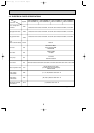
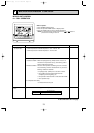
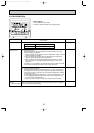
Mark Meaning Function
Power supply for
MA-Remote controller
Main power supply (Indoor unit:208-230V)
Power on ➝ Lamp is lit.
LED on indoor board for service
LED1
Main power supply
Power supply for MA-Remote controller
on ➝ Lamp is lit.
LED2
1
2
3
4
5
5
6
MF
FAN
(
WHT
)
LED2
LED1
2
1
(BLU)
(M-NET)
CN2M
BLU
BLU
TB5
M1
M2
TB2
PULL BOX
FUSE(15A)
BREAKER
(15A)
L1
L2
S
(
SHIELD)
TO OUTDOOR UNIT
BC CONTROLLER
REMOTE CONTROLLER
DC24-30V
2
3
1
CN3A
(BLU)
ORN
ORN
TB15
1
2
TO MA-REMOTE
CONTROLLER
DC8.7-13V
POWER SUPPLY
~ / N 208—230V 60Hz
TO NEXT INDOOR UNIT
3 2 1
(BLK)
GAS
CN29
2 1
(WHT)
LIQUID
CN21
2 1
DS TH23 TH22
(RED)
INTAKE
CN20
(WHT)
LEV
CN60
(GRN)
REMOTE
INDICATION
CN52
2 1
6 5 4 3 2 1
15
(GRN)
VANE
CN6V
6 5 4 3 2 1 2 1
1 2 3 4 5
TH21
(WHT)
DRAIN
CN31
6
LEV
MV
CN25
2 1
CN27
8
7
6
5
4
3
4
3
3
2
1
1
2
1
12345678910
SW3
123456
SW2
12345
SW4
ON
OFF
ON
OFF
ON
OFF
(RED)
ADDRESS
CN81
(RED)
ADDRESS
CN42
(WHT)
REMOTE
SWITCH
CN32
3212 13
DP
X1
X1
(WHT)
CNP
CND
(RED)
FUSE
250V
6A
T
BRN
RED
ORN
YLW
GRN
BLU
BRN
ORN
YLW
RED
WHT
(WHT)
CENTRALLY
CONTROL
CN51
15
RED
BLU
GRN / YLW
See fig : w1
8 7 6 5 4 3 2 1
4321
8
4
0
SW14SWC
2
1
CONNECTION
No.
0
SW11
1ST
DIGIT
0
SW12
2ND
DIGIT
3RD
DIGIT
12345678910
SW1
SW5
230V208V
(RED)
ADDRESS
CN82
(RED)
ADDRESS
CN43
A.B
I.B
G
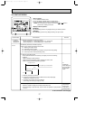
<w2>
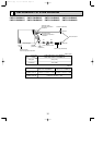
(w2)Use copper supply wire.
PMFY-P06NBMU-E PMFY-P08NBMU-E PMFY-P12NBMU-E PMFY-P15NBMU-E
OC341B--1.qxp 07.7.11 1:29 PM Page 10