


29
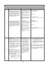
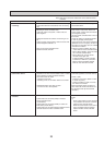
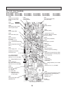
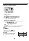
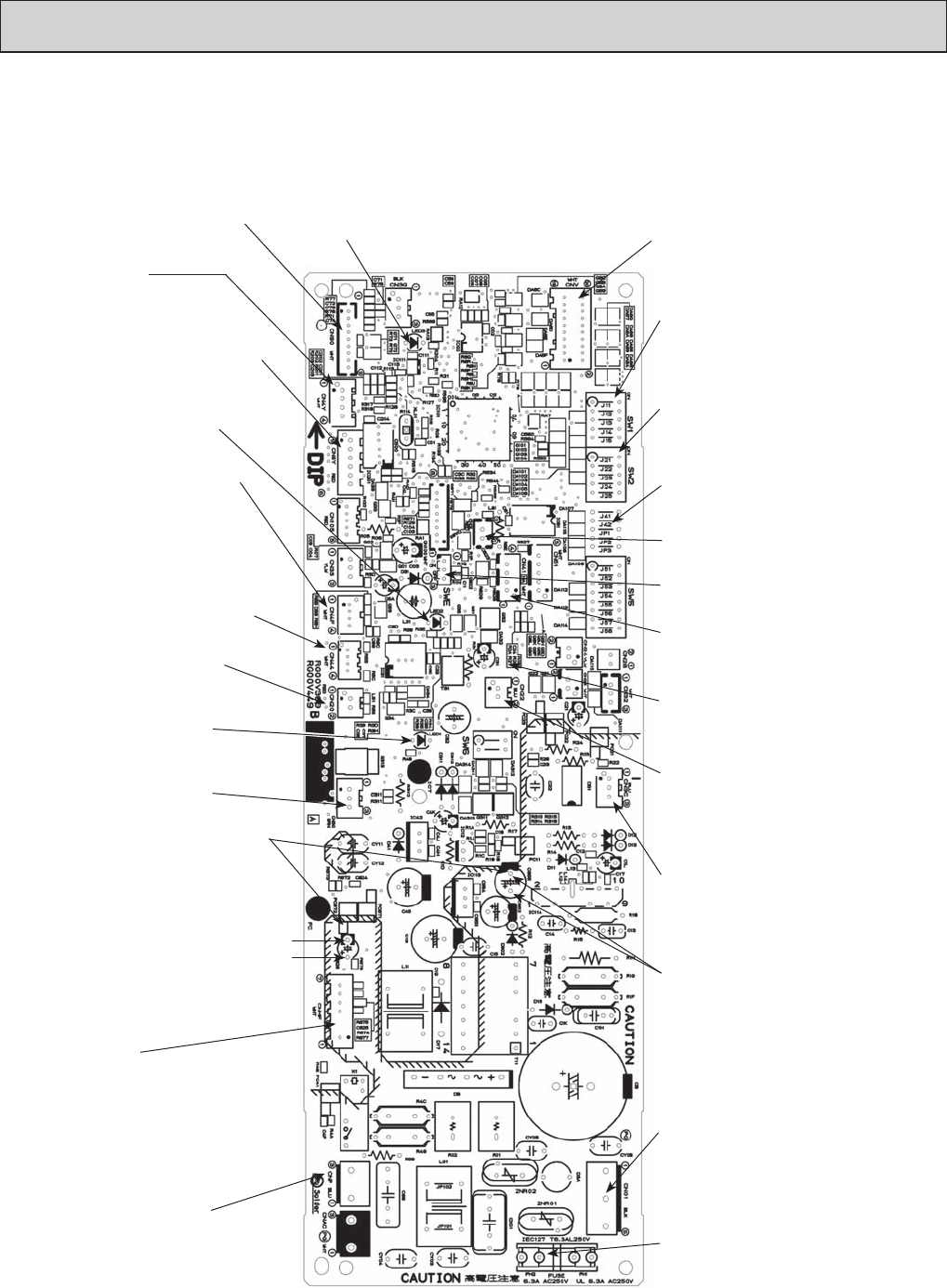
10-7.TEST POINT DIAGRAM
Indoor controller board
PLA-A12BA PLA-A18BA PLA-A24BA PLA-A30BA PLA-A36BA PLA-A42BA
PLA-A12BA
1 PLA-A18BA1 PLA-A24BA1 PLA-A30BA1 PLA-A36BA1 PLA-A42BA1
CN3C
Transmission
(Indoor/outdoor)
(0~24V DC)
SW2
Capacity setting
SW1
Model selection
CN2L
Connector (LOSSNAY)
CN41
Connector
(HA terminal-A)
CN90
Connect to the wireless
remote controller board
(CNB)
CN20
Room temperature thermistor
(TH1)
CN22
Connect to the terminal block (TB5)
(Remote controller connecting wire)
(10.4~14.6V DC)
LED2
Power supply (R.B)
LED1
Power supply (I.B)
LED3
Transmission
(Indoor/outdoor)
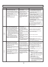
CNP
Drain-pump output (DP)
(208/230V AC)
CN01
Connect to the Terminal Block (TB4)
(Indoor/outdoor connecting line)
Between and
208/230V AC
CNV
Vane motor output (MV)
12V pulse output
SWE
Emergency operation
Jumper wire J41,J42
Pair No. setting for wireless
remote controller
FUSE
6.3A /250V
CNMF
Fan motor
-: DC 294~325V
-: DC15V
-: DC0~6.5V
-: Stop DC0 or 15V
Operation DC7.5V
(0~15V pulse)
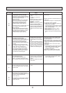
V
SP
: Voltage between pins of
C626
DC0V (FAN stop)
DC1~6.5V (FAN operation)
(Same as (+)–(-) of CNMF)
V
FG
: Voltage between
PC6722 and C955(-)
(Same as (+)–(-) of CNMF)
V
CC
: Voltage between pins of C955
15VDC
(Same as (+)–(-) of CNMF)
CN44
Pipe temperature
thermistor
- : Liquid (TH2)
- :
Condenser/Evaporator
(TH5)
CN4F
Drain float switch (FS)
CN4Y
i-see sensor
CN6Y
i-see sensor motor output
12V DC pulse output
CN30(Only PLA-A
.
BA1)
Connector (LLC)
CN24
(Only PLA-A
.
BA
1)
Connector (Back-up heating)