


23
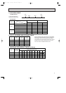
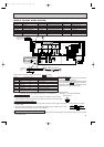
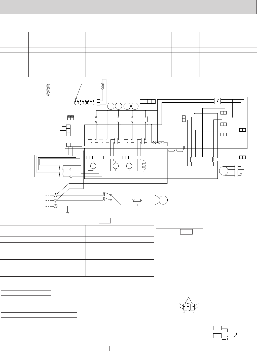
Main function of LED(when both Nos.1 and 2 of are "OFF")
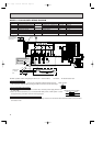
How to use SW1 and 2
● Pressing erases the past check contents
loaded on the microcomputer.
● The output display (light) remains during opera-
tion but pressing displays the past check
contents in flashing mode. Pressing the switch
again retums to output display (light).
NOTES : 1. If the operation stops to function of the protection device, the check display flashes.
2. Symbols used in wiring diagram above are. / :Terminal block, ¤¤¤ :Connector, ¤ :PC board insertion tab.
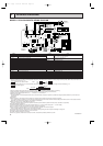
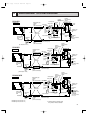
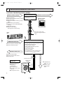
● The connector marked
s
—¤— is to turn the compressor ON-OFF during servicing.
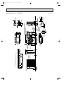
The compressor stops by disconnecting the white connector as shown at the right.
● Since LD8 lights when normal power is turned "ON", check the power supply with the "ON"
or "OFF" LD8.
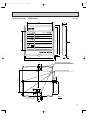
w Since the indoor transformer (T) is connected with 230V power, if 208V power is used,
change the wiring connection as shown in the right figure.
● Since the indoor and outdoor connecting wires has polarity, make sure to connect the same terminal numbers (1,2,3) for indoor
and outdoor units.
CAUTION FOR INDOOR AND OUTDOOR CONNECTING WIRES
CAUTIONS FOR POWER SUPPLY WIRING
CAUTION FOR SERVICING
SW2
SW1
SW3
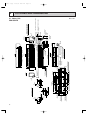
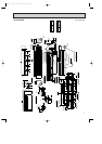
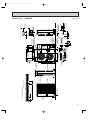
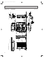
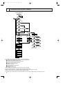
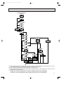
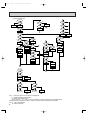
MODELS PUH18EK
WIRING DIAGRAM
LD8
LD7
LD6
LD5
LD4
LD3
LD2
LD1
O.B
SW1
SW2
SW3
OFF
ON
2 1
CN2
RT
LED
1
2
3
TB3
YLW
ORN
BRN
FROM INDOOR UNIT
CONNECTING WIRES
12V DC (polar)
L1
L2
GR
GRN
TB1
POWER SUPPLY
1{ 208/230V
60Hz
3
2
1
CN3
CN4T
4 3 2 1
CN4
4 3 2 1
BRN 12.3V AC
RED 12.3V AC
MF
BLU
BLU
WHT
BLU
WHT
WHT
RED
RED
ORN ORN
C1
MF2
MF1
FC
26C
63H2
63H1
63H1
51CM
5
BRN
BRN
YLW
YLW
YLW
YLW
RED
RED
BLU
63H2
MC
R
C
C
S
2 1
51C
52C
BLU
BLU
WHT
RED
WHT
UR
T W
RED
RED
RED
ORN
BLK
BLK
T
208V
230V
21R
RED
RED
RED
RED
SV
WHT
WHT
TRF
21
S4
BLK
BLK
BLK
BLK
21S4
52C
GRY
GRY
GRY
GRY
52C
WHT
WHT
CH ZNR
R/1
S/2
T/3
BLU BLU
F
HC
WHT
WHT
4
S
A
B
X11X12X13X14
X14
X13 X12 X11
4
3
2
1
C
C1
F<O.B>
FC<O.B>
HC
LD1~LD8
MC
MF
O.B
COMPRESSOR CAPACITOR
FAN CAPACITOR
FUSE<6A>
FAN CONTROLLER
CRANKCASE HEATER
LED<CHECK,SERVICE>
COMPRESSOR
FAN MOTOR<INNER THERMOSTAT>
OUTDOOR CONTROLLER BOARD
RT
SW1•2•3<0.B>
T
TB1,3
X11<O.B>
X12<O.B>
X13<O.B>
OUTDOOR COIL THERMSTOR
<32˚F/15kΩ,77˚F/5.4kΩ>
SELECTOR<CHECK,SERVICE>
TRANSFORMER
TERMINAL BLOCK
CRANKCASE HEATER RELAY
COMPRESSOR RELAY
R.V RELAY
X14<O.B>
ZNR<O.B>
21R
21S4
51C
52C
63H1
63H2
BYPASS VALVE RELAY
VARISTOR
BYPASS VALVE COIL
R.V COIL
OVERCURRENT RELAY
CONTACTOR
CONTROL HIGH PRESSURE SWITCH
PROTECT HIGH PRESSURE SWITCH
LED NO. Output display (light) Check display (flash)
LD1 Compressor indoor command —
LD2 Heating indoor command —
LD3 63H1 ON RT short/open
LD4 Compressor ON 63H2 funcitons
LD5 Outdoor fan ON —
LD6 R.V.coil ON —
LD7 Bypass valve ON RT overheat protection
LD8 Crankcase heater ON Defective input
White connector
RED WHITE
208V
ORANGE
230V
When Power Supply is 208V
w
OC120--1.qxp 24/6/97 12:22 AM Page 23