


3
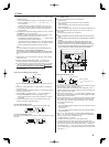
PAR-21MAA
ON/OFF
FILTER
CHECK
OPERATION
CLEAR
TEST
TEMP.
MENU
BACK DAY
MONITOR/SET
CLOCK
ON/OFF
°F°C
°F°C
ERROR CODE
AFTER
TIMER
TIME SUN MON TUE WED THU FRI SAT
ON
OFF
Hr
AFTER
FILTER
FUNCTION
ONLY1Hr.
WEEKLY
SIMPLE
AUTO OFF
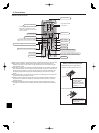
Operation Section
Down
Up
Back
Ahead
Opening the
door.
To preceding
operation number.
To next operation
number.
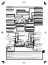
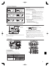
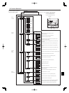
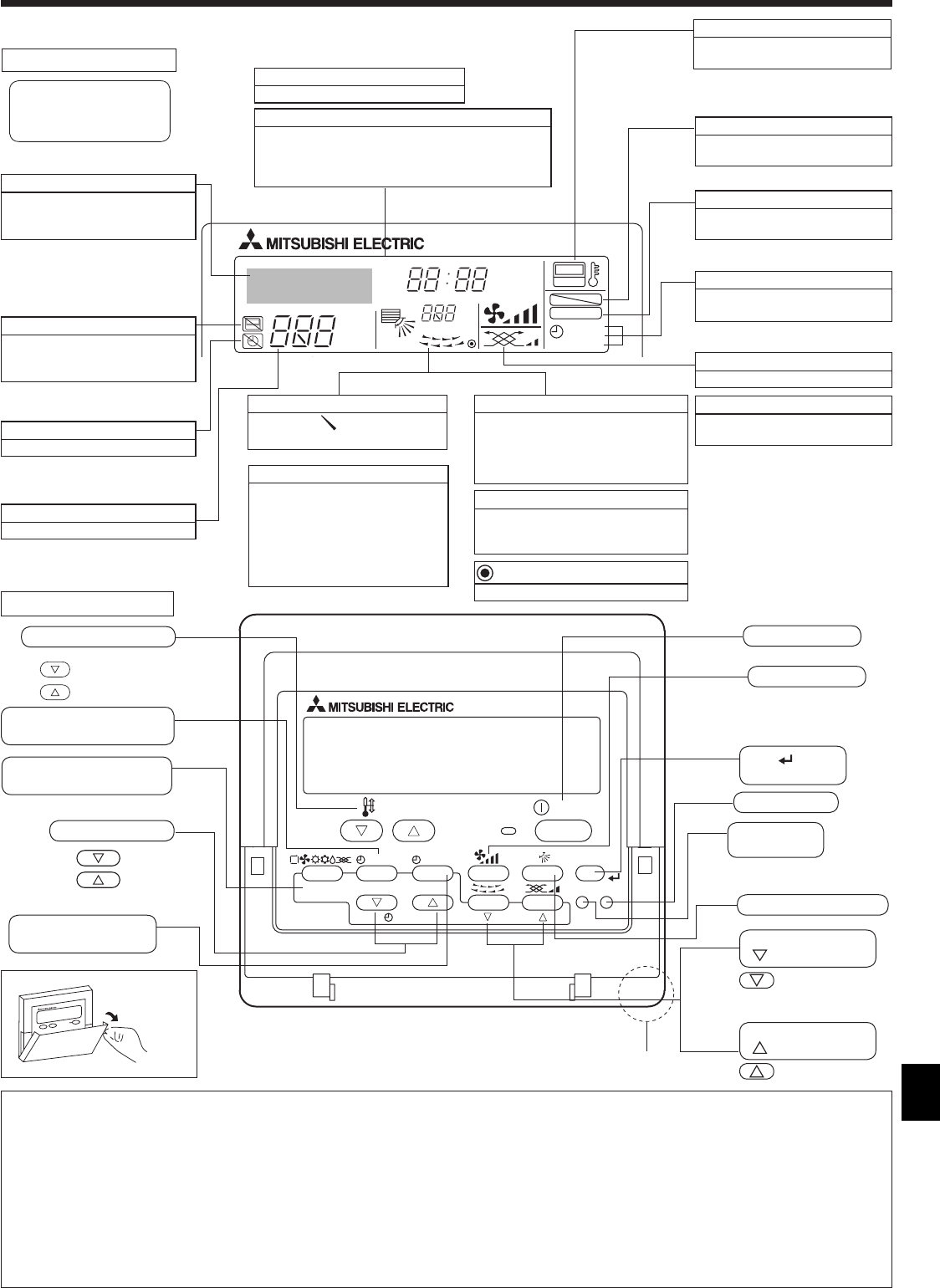
2. Parts Names
Built-in temperature sensor
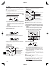
Display Section
Identifies the current operation
Shows the operation mode, etc.
* Multi language display is
supported.
“Centrally Controlled” indicator
Indicates that operation of the
remote controller has been
prohibited by a master controller.
“Timer is Off” indicator
Indicates that the timer is off.
“One Hour Only” indicator
Displayed if the airflow is set to Low
and downward during COOL or DRY
operation mode. (Operation varies
according to model.)
The indicator goes off after one hour
when the airflow up/down direction
also changes.
Temperature Setting
Shows the target temperature.
Airflow up/down direction indicator
The indicator shows the direction
of the outcoming airflow.
Day-of-Week
Shows the current day of the week.
Room Temperature display
Shows the room temperature. The room
temperature display range is 8–39
°
C,
46–102
°
F.
The display blinks if the temperature is less
than 8
°
C, 46
°
F or 39
°
C, 102
°
F or more.
Time/Timer Display
Shows the current time, unless the simple or Auto Off
timer is set.
If the simple or Auto Off timer is set, shows the time
remaining.
Louver display
Indicates the action of the swing louver.
Does not appear if the louver is
stationary.
(Power On indicator)
Indicates that the power is on.
Fan Speed indicator
Shows the selected fan speed.
Ventilation indicator
Appears when the unit is running in
Ventilation mode.
“Locking function” indicator
Indicates that remote controller
buttons have been locked.
“Clean the filter” indicator
Comes on when it is time to clean
the filter.
Timer indicators
The indicator comes on if the
corresponding timer is set.
For purposes of this explanation,
all parts of the display are shown
as lit. During actual operation,
only the relevant items will be lit.
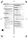
Note:
“PLEASE WAIT” message
This message is displayed for approximately 3 minutes when power is supplied to the indoor unit or when the unit is recovering from a power failure.
Operation mode flashing display
When multiple indoor units are connected to a single outdoor unit and an operation mode is selected for one indoor unit that is different from the
current operation mode of another indoor unit, the operation mode display flashes. Select the same operation mode of the other indoor unit.
“NOT AVAILABLE” message
This message is displayed if a button is pressed to operate a function that the indoor unit does not have.
When the same remote controller is used to operate multiple indoor units, this message is displayed if the main indoor unit is not equipped with
the selected function.
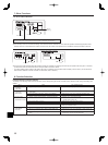
Room temperature display
The indoor unit temperature sensors or the remote controller temperature sensor can be selected to measure the room temperature. The indoor
unit temperature sensors are the initial setting. When the indoor unit temperature sensors are selected to measure the room temperature, the
room temperature measured at the main indoor unit is displayed on the remote controller that operates multiple indoor units.
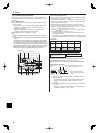
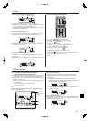
Temperature set buttons
Timer Menu button
(Timer monitor/Timer set button)
Operation mode button
(Back button)
Set Time buttons
Timer On/Off button
(Set Day button)
ON/OFF button
Fan Speed button
Filter
button
(<Enter> button)
Test Run button
Check button
(Clear button)
Airflow up/down button
Louver button
(
Operation button)
Ventilation button
(
Operation button)
Wired Remote-Controller
“Sensor” indicator
Displayed when the remote controller
sensor is used.