


3
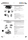
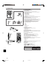
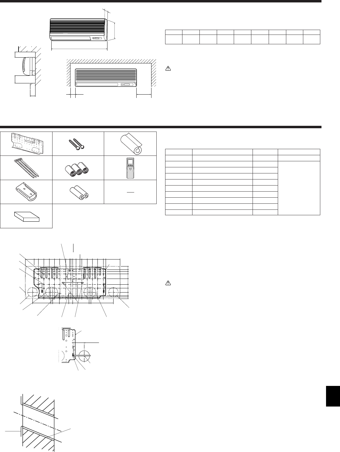
2.1. Outline dimensions (Indoor unit) (Fig. 2-1)
Select a proper position allowing the following clearances for installation and mainte-
nance.
(inch)
Models W D H AEFGH
A12, A18
990 235 340 Min. 30 Max. 130 Min. 180 Min. 50 Min. 150
39 9-1/4 13-3/8
Min. 1-13/16 Max. 5 Max. 7-3/32 Min. 1-31/32 Min. 5-29/32
B Ceiling
C Wall
D Furnishing, etc
Warning:
Mount the indoor unit on a ceiling strong enough to withstand the weight of the
unit.
2.2. Outline dimensions (Outdoor unit)
Refer to the outdoor unit installation manual.
2. Installation location
3. Installing the indoor unit
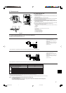
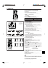
3.1. Check the indoor unit accessories (Fig. 3-1)
The indoor unit should be supplied with the following accessories.
PART NUMBER
ACCESSORY QUANTITY
LOCATION OF SETTING
1 Mount board 1
Fix at the back of the unit
2 Tapping screw 4 × 35 12
3 Pipe cover 1
4 Band 3
5 Felt tape 3
Set inside the unit
6 Wireless remote controller 1
7 Remocon holder 1
8 Alkali batteries (size AAA) 2
9 Mount piece 1
0 Wired remote controller 1 for PKA-A·GA
Fig. 2-1
1
2
3
4
5
6
7
89
Fig. 3-1
Fig. 3-3
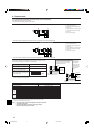
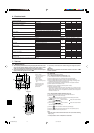
3.2. Installing the wall mounting fixture (Fig. 3-2)
3.2.1. Setting the wall mounting fixture and piping positions
s Using the wall mounting fixture, determine the unit’s installation position
and the locations of the piping holes to be drilled.
Warning:
Before drilling a hole in the wall, you must consult the building contractor.
A Supporting piece I Bottom left pipe slot knockout hole
B Mount board J Bottom right pipe slot (ø90 mm, 3-9/16 inch)
C Main body K Bottom right pipe slot knockout hole
D Slot (6-11 × 20, L Liquid pipe flare connection position
6P-7/16 × 25/32 inch) M Gas pipe flare connection position
E Unit center N Level setting standard
F Bolt hole (14-ø14 mm, V Insert scale.
14P-9/16 inch) Y Hole centre
G Tapping hole (49-ø5 mm, Z Align the scale with the line.
49P-3/16 inch)
H Bottom left pipe slot
(ø90 mm, 3-9/16 inch)
A
C
D
E
B
E
D
C
B
A
F
H
D
W
G H
A Sleeve
B Hole
C (Indoors)
D Wall
E (Outdoors)
3.2.2. Drilling the piping hole (Fig. 3-3)
s Use a core drill to make a hole of 90-100 mm, 3-9/16 to 4 inch diameter in the
wall in the piping direction, at the position shown in the diagram to the left.
s The hole should incline so that the outside opening is lower than the inside
opening.
s Insert a sleeve (with a 90 mm, 3-9/16 inch diameter and purchased locally)
through the hole.
Note:
The purpose of the hole’s inclination is to promote drain flow.
(mm)
B
Y
Z
X
3-15/16
W
16-17/32
19-1/2
15-15/16
14-3/16
11-13/16
9-21/32
7-15/32
5-5/16
2-15/16
1-1/4
25/32
0
1-3/8
31/32
3-3/4
8-1/16
10-1/4
12-19/32
13-19/32
19-1/2
5-29/32
9-1/16
8-9/32
5-1/2
6-11/16
7-15/32
16-23/32
1-9/16
0
0
1-3/8
2-5/32
3-5/32
5-1/8
7-15/32
9-1/16
10-23/32
12-7/32
13-3/8
12-11/16
AE
B
C
D
F
G
H
I
J
K
L
M
N
(inch)
Fig. 3-2
0
}
for PKA-A·GAL
66
66
6 -
88
88
8 are stored in a cut-out section of the packing material (styrofoam).
BG79U874H01_en 05.11.30, 9:233