


3
2. Installation location
3. Installing the indoor unit
Fig. 2-1
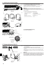
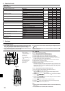
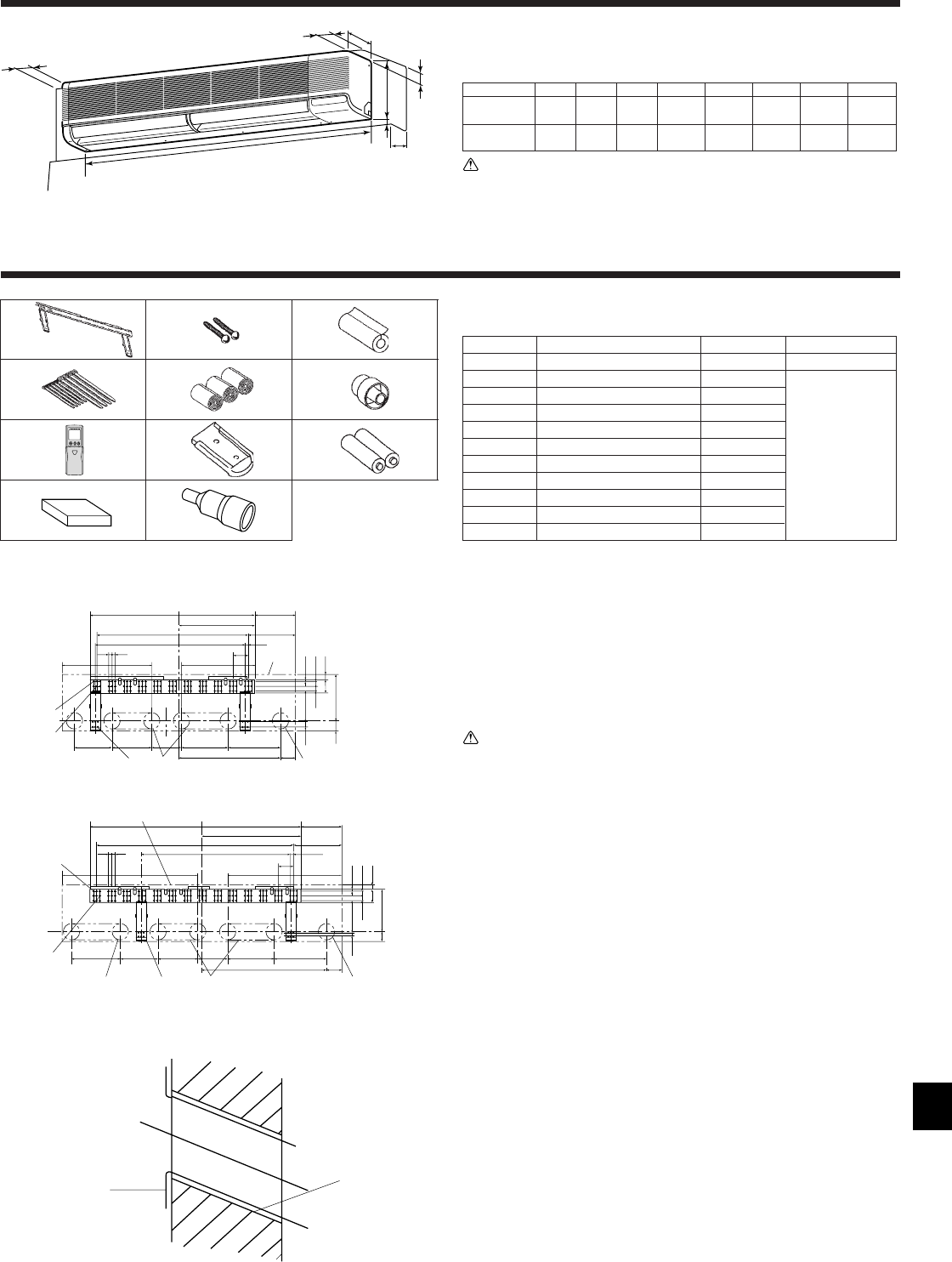
3.1. Check the indoor unit accessories (Fig. 3-1)
The indoor unit should be supplied with the following accessories.
PARTNUMBER
ACCESSORY QUANTITY
LOCATION OF SETTING
1 Wall-fixing bracket 1
Fix at the back of the unit
2 Tapping screw 4 × 35 12
3 Insulation material 2
4 Band
4 (large) + 5 (small)
5 Felt tape 3
6 Drain socket 1 Set inside the unit
7 Wireless remote controller 1
8 Remote controller holder 1
9 Alkali batteries 2
0 Wired remote controller 1 for PKA-A·FA
q Drain adaptor 1
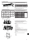
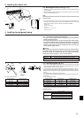
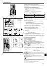
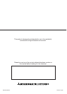
2.1. Outline dimensions (Indoor unit) (Fig. 2-1)
Select a proper position allowing the following clearances for installation and mainte-
nance.
(inch)
Models W D H A B C E F
A24, A30
1400 235 340 Min. 150 Min. 50 Min. 30 Max. 250 Max. 150
55-1/8 9-1/4 13-3/8
Min. 5-15/16
Min. 2
Min. 1-3/16
Max. 10
Min. 5-15/16
A36
1680 235 340 Min. 150 Min. 50 Min. 30 Max. 250 Max. 150
66-5/32 9-1/4 13-3/8
Min. 5-15/16
Min. 2
Min. 1-3/16
Max. 10
Min. 5-15/16
Warning:
Mount the indoor unit on a ceiling strong enough to withstand the weight of the
unit.
2.2. Outline dimensions (Outdoor unit)
Refer to the outdoor unit installation manual.
D
A
C
F
E
H
W
B
1
2
3
4
5
6
7
8
9
A
C
D
E
B
Fig. 3-1
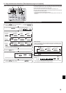
Fig. 3-3
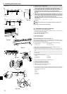
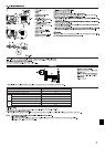
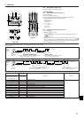
3.2. Installing the wall mounting fixture (Fig. 3-2)
1) Setting the wall mounting fixture and piping positions
s Using the wall mounting fixture, determine the unit’s installation position
and the locations of the piping holes to be drilled.
Warning:
Before drilling a hole in the wall, you must consult the building contractor.
A Indoor unit center line
B Left drain range
C Right drain range
D Hole for tapping screw
E Bolt hole
F Hole for tapping screw
G Contour of the unit
H Knockout hole for left rear piping
I Rear piping access hole (90-100 mm, 3-9/16 to 4 inch dia.)
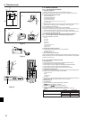
2) Drilling the piping hole (Fig. 3-3)
s Use a core drill to make a hole of 90-100 mm, 3-9/16 to 4 inch diameter in the
wall in the piping direction, at the position shown in the diagram to the left.
s The hole should incline so that the outside opening is lower than the inside
opening.
s Insert a sleeve (with a 90 mm, 3-9/16 inch diameter and purchased locally)
through the hole.
Note:
The purpose of the hole’s inclination is to promote drain flow.
A Sleeve
B Hole
C (Indoors)
D Wall
E (Outdoors)
(mm)
38-31/32
9-21/32
11-7/32
17-29/32
13/32×3-19/32= (35-13/16)
3/4
13/32
7-1/4
11-1/32
2-3/8
1-3/16
1-3/161-3/16
1-5/32
3-5/323-5/32
35-7/16
3-19/32
3-17/32
24-1/32
12-3/811-1/329-7/168-27/32
23/3223/32
A
B
C
G
IHF
E
D
50
35-7/16 3/4
3-19/32
11-5/8 8-27/32 9-71/16
7-3/32
11-1/32 12-3/8
3-17/32
29-17/32
2-3/82-3/8
11-1/32
1-5/32
1-3/161-3/16
1-3/16
13/327-1/4
1/2×3-19/32=(46-9/16)
9-21/32
11-7/32
23-7/16
IHH
E
D
B
G
A
C
F
23/3223/32
7-3/327-3/32
3-5/323-5/32
(inch)
■ A24, A30
■ A36
Fig. 3-2
0
}
for PKA-A·FAL
77
77
7 -
99
99
9 are stored in a cut-out section of the packing material (styrofoam).
q