


8
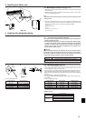
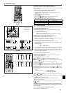
6. Electrical work
S1
S2
S3
L1
L2
GR
BLUE
BLUE
YELLOW
YELLOW
CND
CND
ORANGE
CND
ORANGE
S1
S2
S3
L1
L2
GR
YELLOW
BLUE
BLUE
YELLOW
CND
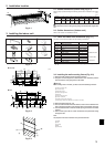
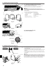
6.1.2. Separate indoor unit/outdoor unit power supplies (A-control application)
The following connection patterns are available.
The outdoor unit power supply patterns vary on models.
1:1 System
S1
S2
L1
L2
GR
GR
1
2
L1
L2
S1
S2
S3
S3
A
B
C
G
D
B
E
F
* Affix a label B that is included with the manuals near each wiring diagram for the indoor and outdoor units.
A Outdoor unit power supply
B Wiring circuit breaker or isolating switch
C Outdoor unit
D Indoor unit/outdoor unit connecting cords
E Remote controller (Only for PKA-A·FA)
F Indoor unit
G Indoor unit power supply
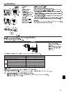
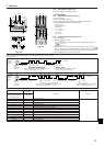
If the indoor and outdoor units have separate power supplies, refer to the table at the
below. Change the indoor unit electrical box wiring refering to the figure in the right
and the DIP switch settings of the outdoor unit control board.
ON
OFF 1 2
(SW8)
3
Indoor unit electrical box connector con-
nection change
Label affixed near each wiring diagram
for the indoor and outdoor units
Outdoor unit DIP switch settings (when
using separate indoor unit/outdoor unit
power supplies only)
Indoor unit specifications
Required
Required
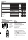
*1. Max. 50 m, 165 ft
*2. The 10 m, 30 ft wire is attached in the remote controller accessory. Max. 500 m, 1500 ft
*3. The figures are NOT always against the ground.
Notes: 1. Wiring size must comply with the applicable local and national code.
2. Use copper supply wires.
3. Use wires rated 300V or more for the power supply cables.
4. Install an earth longer than other cables.
Indoor unit model
Indoor unit power supply
Minimum circuit ampacity
Maximum rating of overcurrent protective device
Indoor unit power supply
Indoor unit power supply earth
Indoor unit-Outdoor unit *1
Indoor unit earth
Remote controller-Indoor unit *2
Indoor unit L1-L2 *3
Indoor unit-Outdoor unit S1-S2 *3
Indoor unit-Outdoor unit S2-S3 *3
Remote controller-Indoor unit *3
PKA
Single 208/230 V, 60 Hz
1 A
15A
2 × Min. AWG16
1 × Min. AWG16
2 × AWG22 (polar)
–
2 × AWG22 (Non-polar)
AC 208/230 V
–
DC24 V
DC12 V
Circuit
rating
Wiring
Wire No. × size
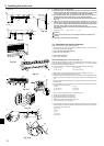
Connectors (connections when shipped
from the factory are for indoor unit power
supplied from outdoor unit)
Indoor unit power supplied from outdoor unit
(when shipped from factory)
If the indoor and
outdoor units have
separate power
supplies, change the
connections of the
connectors as shown
in the following
figure.
Connectors
Indoor unit
control board
Separate indoor unit/outdoor unit power
supplies
Indoor unit
control board
* There are three types of labels (labels A, B, and C). Affix the appropriate labels to
the units according to the wiring method.
6. Electrical work
6.2. Remote controller
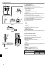
6.2.1. For wired remote controller
1) Installing procedures
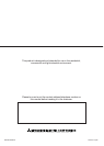
(1) Select an installing position for the remote controller. (Fig. 6-2)
The temperature sensors are located on both remote controller and indoor unit.
s Procure the following parts locally:
Two piece switch box
Thin copper conduit tube
Lock nuts and bushings
A Remote controller profile
B Required clearances surrounding the remote controller
C Installation pitch
(2) Seal the service entrance for the remote controller cord with putty to prevent pos-
sible invasion of dew drops, water, cockroaches or worms. (Fig. 6-3)
A For installation in the switch box:
B For direct installation on the wall select one of the following:
• Prepare a hole through the wall to pass the remote controller cord (in order to run
the remote controller cord from the back), then seal the hole with putty.
• Run the remote controller cord through the cut-out upper case, then seal the cut-
out notch with putty similarly as above.
B-1. To lead the remote controller cord from the back of the controller:
B-2. To run the remote controller cord through the upper portion:
(3) For direct installation on the wall
C Wall
D Conduit
E Lock nut
F Bushing
G Switch box
H Remote controller cord
I Seal with putty
J Wood screw
2) Connecting procedures (Fig. 6-4)
1 Connect the remote controller cord to the terminal block.
A To TB5 on the indoor unit
B TB6 (No polarity)
3) Two remote controllers setting
If two remote controllers are connected, set one to “Main” and the other to “Sub”. For
setting procedures, refer to “Function selection of remote controller” in the operation
manual for the indoor unit.
6.2.2. For wireless remote controller
1) Installation area
• Area in which the remote controller is not exposed to direct sunshine.
• Area in which there is no nearby heating source.
• Area in which the remote controller is not exposed to cold (or hot) winds.
• Area in which the remote controller can be operated easily.
• Area in which the remote controller is beyond the reach of children.
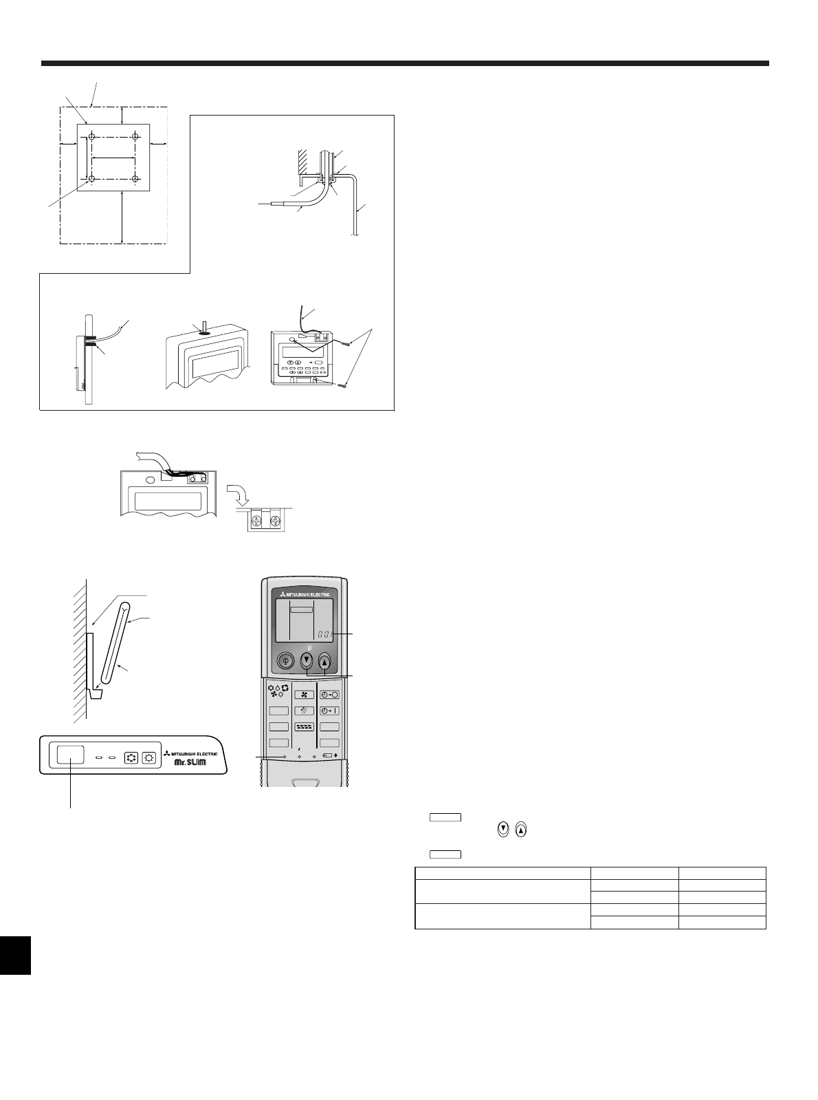
2) Installation method (Fig. 6-5)
1 Attach the remote controller holder to the desired location using two tapping screws.
2 Place the lower end of the controller into the holder.
A Remote controller
B Wall
C Display panel
D Receiver
• The signal can travel up to approximately 7 meters, 23 ft (in a straight line) within 45
degrees to both right and left of the center line of the receiver.
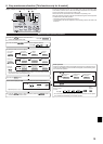
3) Setting (Fig. 6-6)
1 Insert batteries.
2 Press the SET button with something sharp at the end.
MODEL SELECT
blinks and Model No. is lighted.
3 Press the temp
button to set the Model No.
4 Press the SET button with something sharp at the end.
MODEL SELECT
and Model No. are lighted for three seconds, then turned off.
B-1. B-2.
Fig. 6-3
Indoor Outdoor A Model No.
PLA, PCA, PKA (A12, A18)
heat pump models 001
cooling only models 033
PKA (A24, A30, A36)
heat pump models 003
cooling only models 035
Fig. 6-5
Fig. 6-6
Fig. 6-2
Fig. 6-4
ON
OFF
STAND
BY
COOL HEAT
D
B
1
C
A
2
1-3/16
1-37/64
1-3/16
1-3/16
4-23/32
3-9/32
A
B
C
F
A
H
C
D
E
G
I
I
I
H
B
A
AB TB6
B
ON/OFF TEMP
FAN
VANE
TEST RUN
AUTO STOP
AUTO START
h
min
LOUVER
MODE
CHECK
RESETSET CLOCK
MODEL SELECT
2,4
3
A
J
H