


30
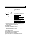
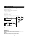
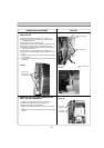
3. REMOVING THE ELECTRICAL BOX
(1) Remove the panel and the corner box. (Refer to 1.)
(2) Remove the front and side electrical box covers (each 1
screw).
(3) Remove the indoor / outdoor connecting wire from termi-
nal block (TB4).
(4)
Disconnect the connectors on the indoor controller board.
(5) Disconnect the connector for ground wire.
(6) Remove the screw on lower side of the electrical box.
(See Photo 5)
(7) Push up the upper fixture catch to remove the box, then
remove it from the box fixture.
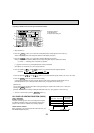
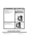
4. REMOVING THE NOZZLE ASSEMBLY (with VANE
and VANE MOTOR) AND DRAIN HOSE
(1) Remove the panel and corner box. (Refer to 1.)
(2) Remove the electrical box covers. (Refer to 2.)
(3) Disconnect the vane motor connector (CN151) on the
indoor controller board.
(4) Pull out the drain hose from the nozzle assembly, and
remove nozzle assembly. (See Photo 5)
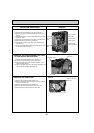
Photo 4
Photo 5
Photo 6
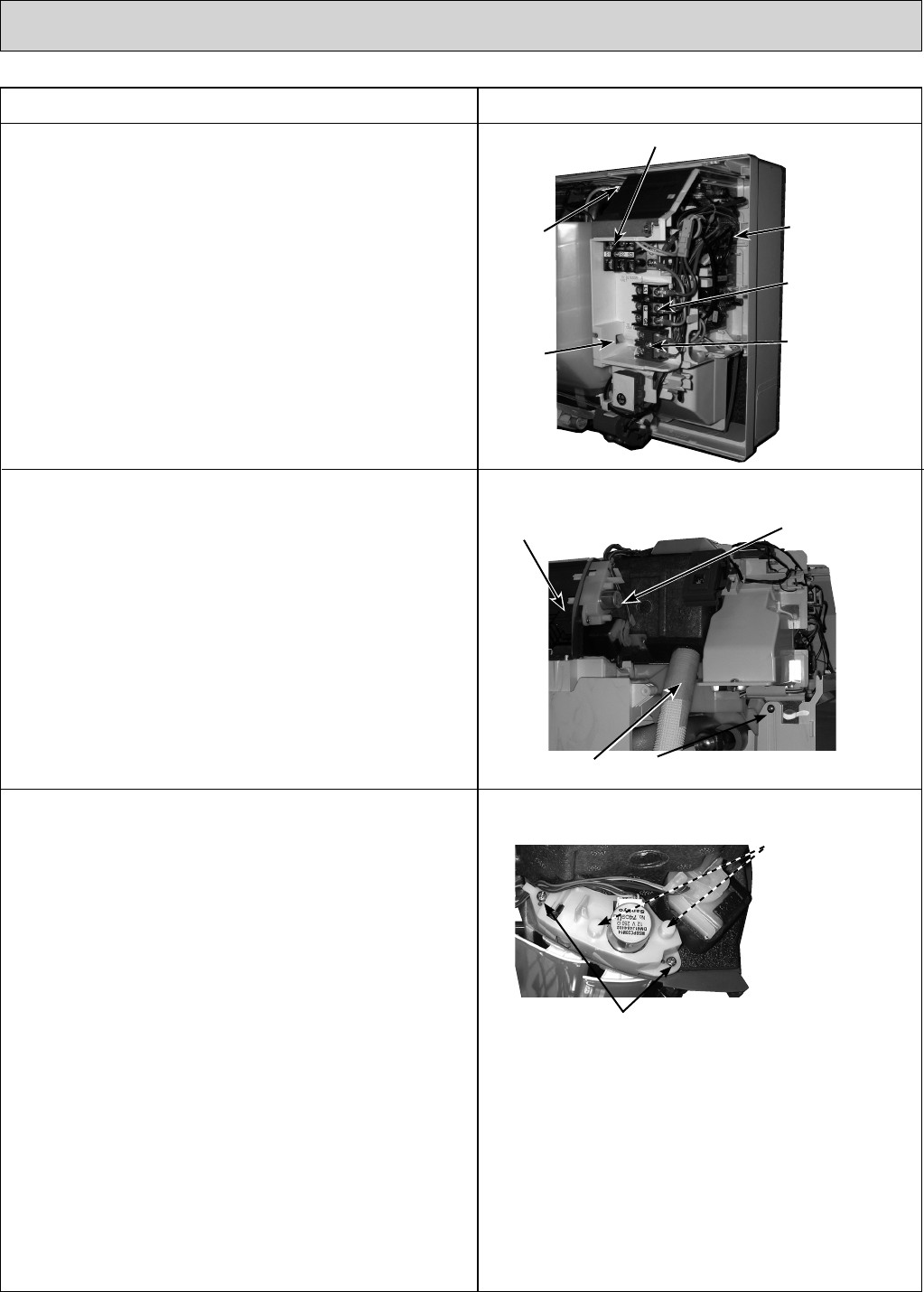
5. REMOVING THE VANE MOTOR
(1) Remove the nozzle assembly. (Refer to 4.)
(2) Remove 2 screws of the vane motor unit cover, and pull
out the vane motor unit.
(3) Remove 2 screws of the vane motor unit.
(4) Remove the vane motor from the vane motor unit.
(5) Disconnect the connector from the vane motor.
Screw of electrical box
Drain hose
Vane motor
Nozzle assembly
Screws of the vane
motor unit
Screws of the vane motor unit cover
(see the bottom)
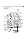
PHOTOSOPERATION PROCEDURE
Indoor controller
board (I.B.)
Terminal block (TB4)
Electrical
box
Terminal block
(TB2) (option)
Terminal block
(TB5) (only PKA-KA)
Connector
for ground
wire