18
8
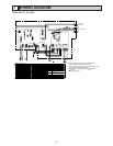
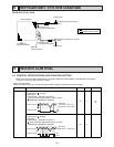
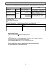
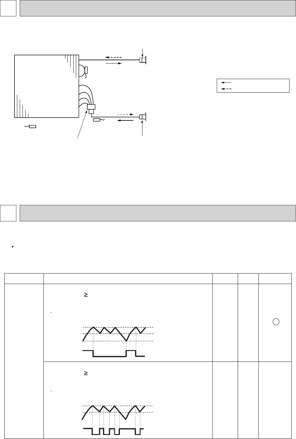
REFRIGERANT SYSTEM DIAGRAM
PEAD-A24, 30, 36, 42AA
Thermistor TH2
Pipe temperature(Liquid)
Distributor
with strainer (#50)
Thermistor TH5
(Cond./ Eva.temperature)
Thermistor TH1
(Room temperature)
Refrigerant flow in cooling
Refrigerant flow in heating
Strainer (#50)
Strainer (#50)
Heat exchanger
Refrigerant GAS pipe connection
(Flare)
Refrigerant LIQUID pipe connection
(Flare)
9
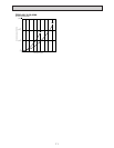
HEATER CONTROL
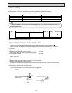
9-1. CONTROL SPECIFICATIONS AND FUNCTION SETTING
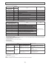
Table 1 shows how the field-installed heater is controlled. Select the desired pattern in the table below, and set the
Function on the indoor units as shown in Table 1.
Table.1 [Function table]
Select unit numbers 01 to 03 or all units (AL[wired remote controller] / 07[wireless remote controller])
*Refer to the Installation Manual for function settings.
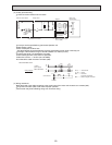
Mode Setting Mode no. Setting
Initial setting
Heater control
23 1
23 2 -
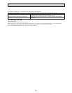
Heater OFF
Inlet air temp. set temp.
Heater ON
Inlet air temp. < set temp.-4.5˚F(2.5˚C)
The fan will stop and the heater will turn off when
[DEFROST] or [ERROR] is displayed.
The fan will drive and the heater will turn on when
[DEFROST] or [ERROR] is displayed.
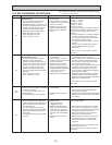
Set temp.
Set temp.-1.8
˚
F(1
˚C
)
Set temp.-4.5
˚
F(2.5
˚C
)
Inlet air temp.
Heater output
OFF
ON
Heater OFF
Inlet air temp. set temp.
Heater ON
Inlet air temp. < set temp.-1.8˚F(2.5˚C)
Set temp.
Set temp.-1.8
˚
F(2.5
˚C
)
Inlet air temp.
Heater output
OFF
ON


