


- 89 -
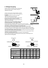
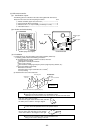
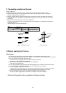
Construct the earth connection.
All electrical work must be carried out by a suitable qualified electrical trades-person and in
accordance with local supply authority requirements and associated regulators.
The range of working voltage is within 10% voltage of power supply.
The outdoor unit is to be wired directly from an electrical distribution board either by a circuit
breaker (preferred) or HRC fuse.
Fix power source wiring to control box by using buffer bushing for tensible force (PG
connection or the like). Connect control wiring to control terminal block through the knockout
hole of control box using ordinary bushing.
Note:
Earth wiring must be connected.
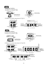
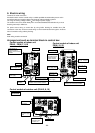
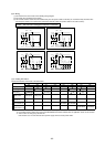
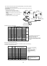
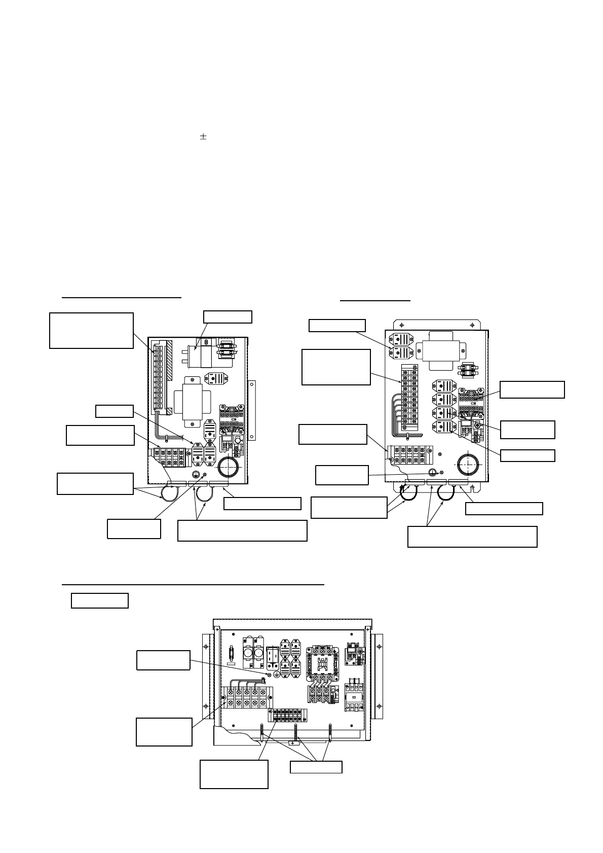
Arrangement such as terminal block in control box
Electric wiring
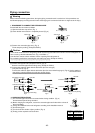
6.
Control module of indoor unit
PEH-5, PE(H)-7, 8,10
Control module of indoor unit
PE(H)-15, 20
Control module of outdoor unit (PUH-5, 8, 10)
Side blow
Screw for earth
connection
Terminal block for
power supply wires
Bush and band for the
power supply
Terminal block for
connection wires to
Outdoor unit and remote
controller
Bush for the thermistor
Bush and band for the connection wires
to Outdoor unit and remote controller
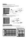
PE(H)-7 only
PEH only
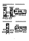
F2(3.15A)
F1(3.15A)
Tr
HZ1 CZ1
TB2
52F,51F1
LN
C
FZ
30FZ
Terminal block for
connection wires to
Outdoor unit and
remote controller
Terminal block for
power supply wires
Screw for earth
connection
Bush and band for the
power supply
Bush for the thermistor
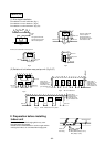
PEH-15, 20 only
PEH-15, 20 HZ1-1
PE-15, 20 FZ
PEH-15, 20 52F&51F1
PE-15, 20 52F1&51F1
Bush and band for the connection wires
to Outdoor unit and remote controller
PEH-15,20 only
F2(3.15A)
F1(3.15A)
HZ1-2
HZ1-1
CZ1-2
CZ1-1
IN CASE OF G03
TB2
52F&51F
Tr
TB3
FZ30FZ
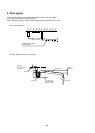
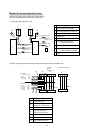
L1 L2 L3 N
65432114131211
Screw for earth
connection
Terminal block for
connection wires
to Indoor unit
Band for wires
Terminal block
for power supply
wires
F3
CZ2
T2
26D
TB1
TB5&6
X1
51F2
52C
&
51C
HZ2
X2 30CZ
T1
F3 3.15A