- 94 -
(4) Wiring example (For metal piping)
The grounding wire must be of the same
diameter as the power cable wires.
Table above is an example.
The selection of other capacities should be
determined in accordance with the relevant
standards.
Over current
protection switch
PEH - 5
PE(H) - 7
Power
cable
2.0mm
2.0mm
2
2
Earth cable
2.0mm over
PE(H) - 8
PE(H) -10
PE(H) -15
PUH - 5
PU(H) - 7
PU(H) -20
PU(H) -10
PU(H) -15
15A
2
2.0mm over15A
2
2.0mm
2.0mm
2
2
2.0mm over15A
2
2.0mm over15A
2
2.0mm
8mm
2
2
2.0mm over30A
2
8mm over50A
2
8mm
8mm
2
2
8mm over50A
2
8mm over
50A
2
14mm
14mm
2
2
14mm over60A
2
14mm over100A
2
15A
15A
15A
15A
30A
50A
50A
50A
60A
100A
Control
wiring
Cable or
wire of
0.75mm
(24VDC)
2
PE(H) -20
2.0mm
2
2.0mm over30A
2
30A
22mm
2
22mm over125A
2
125A
Cable or
wire of
0.75mm
(24VDC)
2
PU(H) - 8
Breaker
capacity
(5) Selecting earth leakage breaker (NV)
To select NF or NV instead of a combination of Class B fuse switch use the following.
In the case of Class B fuse rated 15A.
NV is a product of MITSUBISHI
ELECTRIC.
Table above is an example. The
selection of other capacities
should be determined in
accordance with the relevant
standards.
Note.
All electrical wiring must be comply
with local electrical authority
regulations.
Fuse
(class B)
Earth leakage breaker
(with over-load protection)
15A15A NV30-CA 30mA 0.1s or lessPEH - 5
PE(H) - 7 15A15A NV30-CA 30mA 0.1s or less
30A30A NV50-CP 30mA 0.1s or lessPE(H) -20
PUH - 5 50A50A NV50-CA 100mA 0.1s or less
50A50A NV50-CA 100mA 0.1s or lessPU(H) - 7
100A100A NV100-CP 100mA 0.1s or lessPU(H) - 15
125A125A
NV225-CP 100mA 0.1s or lessPU(H) - 20
60A60A NV60-CA 100mA 0.1s or lessPU(H) - 10
50A50A NV50-CA 100mA 0.1s or lessPU(H) - 8
30A30A NV50-CP 30mA 0.1s or lessPE(H) -15
PE(H) - 8 15A15A NV30-CA 30mA 0.1s or less
PE(H) - 10 15A15A NV30-CA 30mA 0.1s or less
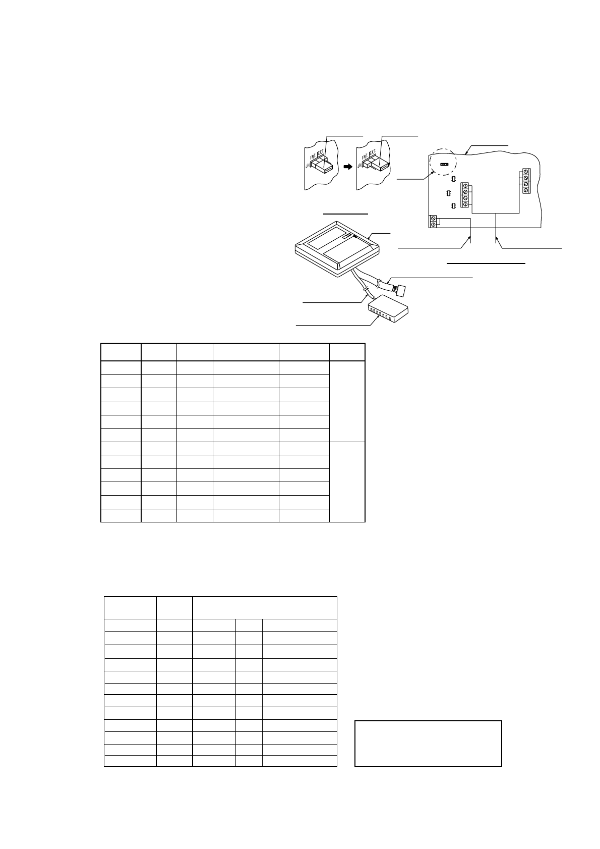
(3)-5. How to connect the external sensor (PAC-SE40TSA) to LCD remote controller.
This controller is set for using internal sensor.
If you need the external sensor, please consult your dealer and purchase option external sensor.
(PAC-SE40TSA)
And please change below method.
Section A
Wiring of external sensor
Printed board
Wiring of
LCD remote controller
EXT SENSOR
COMP2
COMP1
4W V
ERROR
JH
INT / EXT
24VAC (L)
24VAC (N)
FAN HI
FAN LO
Shunt jumper
Shunt jumper
Replace JH (Shunt jumper) from
INT side to EXT side.
Detail section A
LCD remote controller inside
Wiring of LCD remote controller
Wiring external sensor
External sensor PAC-SE40TSA
Cover
1. Remove the cover of LCD remote controller.
2. Connect the wire of external sensor to terminal as
below.
3. Replace the shunt jumper from "INT" side to "EXT" side
as below.
4. Check above connection. (Refer to PAC-SE40TSA
Installation manual.)
5. Attach the cover of LCD remote controller.


