


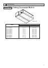
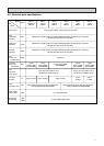
11
PDFY-P36·48NMU-E
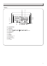
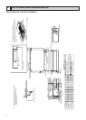
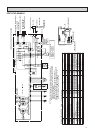
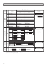
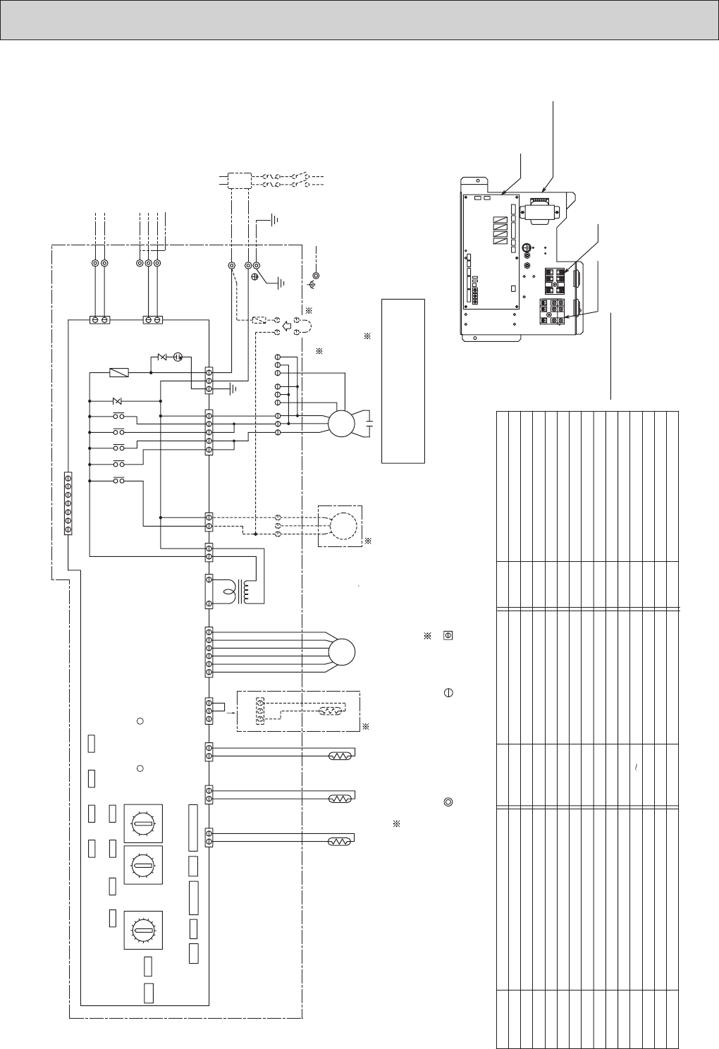
PARTS LOCATION
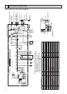
Varistor
ZNR1,ZNR901
G
54321
(Green)
CN22
(Yellow)
CN24
(White)
CN25
NOTE1
(Blue)
(Red)
(White)
DP
T1
T2
T3
AC250V
5A F
( )
( )
AC250V
6.3A T
S(SHIELD)
TB15 (TRANSMISSION TERMINAL BED)
TB5 (TRANSMISSION TERMINAL BED)
TB2
F2
L2
L1
ZNR901
901
CN2M
(Blue)
C
1
2
4
2
1
4
2
1
MF
CND(Red)
5
3
1
X07
I.B.
1
1
2
M1
M2
3
X04
X05X06
X01
1
9
3
5
7
F
1
2
4
CNP(Blue)
3
1
(White)
CNT
1
3
1
3
T
CN60(White)
1
2
3
4
5
6
LEV
TH23TH22
TH21
(White)
CN90
CN3A
(Blue)
DSA1
ZNR1
CN31
13
DS
3
1
2
CN7V(White)
CN51
CN27
CN41
CN52
(White)
CN32
(White)
(Green)
(White)
(Red)
LED2
LED1
SW11
(1st digit)
SW12
(2nd digit)
SW14
(Connection No.)
SW5
SW8
SW2
SW3
SW4
SW1
SW7
12
1
2
1
2
2
1
CN21(White)CN20(Red) CN29(Black)
CN31(White)
CN3T(Red)
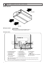
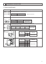
INSIDE SECTION OF CONTROL BOX
A
Connector
Connector
CN25
CN22
Connector CNV
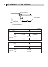
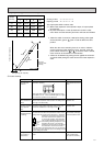
Color/External static pressure
White/Low
Red/Middle
Blue/High
<T1>,T2,T3 Terminal
Connector
Power supply (Remote controller) LED2
Power supply (I.B.) LED1
Connector (centrally control)
Connector (remote indication) CN52
CN51
Connector (HA terminal-A) CN41
Connector (centrally control) CN32
CN27
8
7
6
5
4
3
2
1
0
9
1
2
3
4
5
6
7
8
9
0
0
9
8
7
6
2
1
5
4
3
F
E
D
C
B
A
Connector CN24
Drain sensor
Drain pump <DP>
<DS>
Inside < > is the optional parts.
<F2> Fuse AC250V 5A F
NOTE;1.The part of the broken line indicates the circuit for optional parts.
2. A in the chart is the connector for a drain pump test run operation.
(The Drain Pump operates continuously if the connector is inserted
and the power is supplied.)
After the test run, make sure to remove the A connector.
3.The wirings to TB2,TB5,TB15 shown in chained line are field work.
4.Mark indicates terminal bed, connector, board insertion
connector or fastening connector of control board.
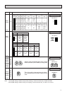
NAME SYMBOL NAME SYMBOL
SW8
SW7
Transmission terminal bed TB15
SYMBOL
MF
C
I.B.
F901
T
LEV
Fan motor
Capacitor (for MF)
Electronic linear expan. valve
Indoor controller board
Transformer
Thermistor (inlet temp.detection)
Switch (1st digit address set)
SW2
SW3
TH21
TH22
TH23
SW11
SW12
SW14
SW1
SW4
TB2
TB5 Transmission terminal bed
Power source terminal bed
X01,X04 X07
SYMBOL EXPLANATION
NAME
SW5
Fuse AC250V 6.3A T
TB2
TB5,TB15
I.B.
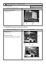
CONTROL BOX
A connector is
attached to the
drain lift up
mechanism,
which is an
optional part.
NOTE 1,2
Switch(for mode selection 3)
Switch(for model selection)
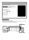
POWER SUPPLY
208/230V 60Hz
TO NEXT INDOOR UNIT
PULL BOX
FUSE(15A)
BREAKER(15A)
TO MA REMOTE
CONTROLLER
Thermistor (piping temp.detection/liquid)
Thermistor (piping temp.detection/gas)
Switch (for mode selection)
Switch (for capacity code)
Switch (2nd digit address set)
Switch (connection No.set)
Switch(for mode selection)
Switch(for model selection)
Aux.relay
Switch(for voltage selection)
TO OUTDOOR UNIT
BC CONTROLLER
REMOTE CONTROLLER
TO DUCT
NOTE1
Pressure
Pressure
Pressure