– 5 –
12V
24V
R
NL
ABS
12VDC
GND
T B 2 T B 3
L/L1 N/L2
Power source
EU:~220-240V 50Hz
US:~208-230V 60Hz
Circuit breaker
Power cable
Ground
Protective earth cable
(Grounding cable)
TB1
Fix the power line
Power cable
Protective
earth cable
TB1
Fig.4-2
(L/L1)
(N/L2)
EU : ~220V-240V 50Hz
US : ~208V-230V 60Hz
Power line terminal
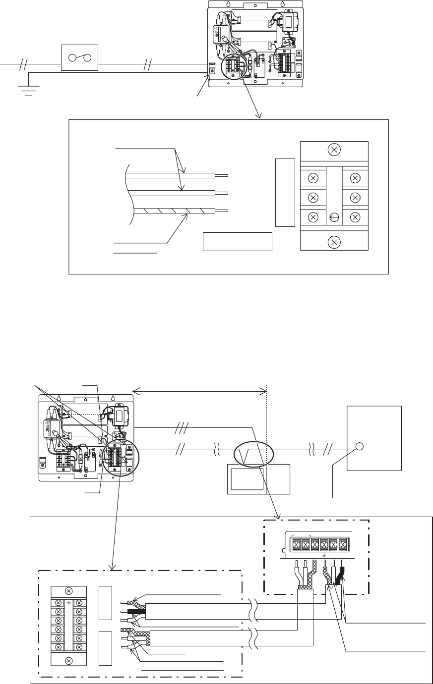
2. Power line
Wire the power cable and protective earth cable (grounding cable) to L/L1,N/L2 and the earth line (grounding line) terminals on the TB1
as shown in the Fig.4-2.
3. DC Power Supply and M-NET Transmission Line
The DC power line and M-NET transmission line connect as shown in Fig. 4-3. The DC power line has a 12VDC and a GND polarity.
Connect it to the terminals in accordance with the polarity. Connect the M-NET transmission line to the A, B (non-polarity) and S
(shield) terminal block.
Fig.4-3
12V
24V
NL
R
GND
12VDC
SBA
GND12VDC
SBA
POWER
M-NET
Controller rear surface
ABS
12VDC
GND
T B 2 T B 3
TB3
Fix the power line.
TB2
Within 10m
DC power supply line
(DC12V) ❈Polarized
M-NET transmission line
(Centralized control line)
Central controller
Outdoor
Unit
TB7
DC power supply line terminal
M-NET transmission
line terminal
TB3
M-NET transmission A,B line
(Non-polarity DC24V)
TB2
Shield
(Grounding cable)
Function earthing(grounding)
DC 12V power supply line (Polarity)
DC 12V power supply line
(Polarity)
12VDC : +12V, GND : 0V
Function earthing(grounding)
*EU shows L/N and the US shows L1/L2.
*US: USA and
Canada
EU/US


