


11
GBDFEINLPGRRUTRCZSVHGPO
Caution:
Install wiring so that it is not tight and under tension. Wiring under tension
may break, or overheat and burn.
9.3. Connecting electrical connections
Please identify the model name of the operation manual attached on the terminal
bed box cover with that shown on the rating name plate.
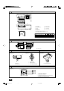
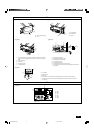
1. Remove the screw (2pcs) holding the cover to dismount the cover.
[Fig. 9.3.1] (P.5)
A Screw holding cover (2pcs) B Cover
2. Open knockout holes
(Recommend to use a screwdriver or the like for this work.)
[Fig. 9.3.2] (P.5)
A Terminal bed box B Knockout hole
C Remove
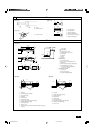
3. Fix power source wiring to terminal bed box by using buffer bushing for tensile
force. (PG connection or the like.) Connect transmission wiring to transmission
terminal bed through the knockout hole of terminal bed box using ordinary
bushing.
[Fig. 9.3.3] (P.5)
E Use PG bushing to keep the weight of the cable and external force from being
applied to the power supply terminal connector. Use a cable tie to secure the
cable.
F Power source wiring G Tensile force
H Use ordinary bushing I Transmission wiring
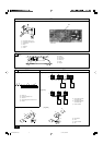
4. Connect the power source, Earth, transmission and remote controller wiring.
The dismounting of the terminal bed box is not needed.
[Fig. 9.3.4] (P.5)
J Power source terminal bed K Terminal bed for indoor transmission
L Terminal bed for remote controller M To 1-phase power source
N Transmission line DC 30 V
O Terminal bed for outdoor transmission line (TB3)
P Transmission line to the remote controller, terminal bed for indoor unit and BC
controller
[Shield wire connection]
[Fig. 9.3.5] (P.5)
A Terminal bed B Round terminal
C Shield wire
D The earth wire from two cables are connected together to the S terminal. (Dead-
end connection)
E Insulation tape (To keep the earth wire of the shielded cable from coming in con-
tact with the transmission terminal)
5. After wiring is complete, make sure again that there is no slack on the connec-
tions, and attach the cover onto the terminal bed box in the reverse order of
removal.
Notes:
• Do not pinch the cables or wires when attaching the terminal bed box
cover. Doing so may cause a risk of disconnection.
• When accommodating the terminal bed box, make sure that the connec-
tors on the box side are not removed. If removed, it cannot operate nor-
mally.
9.1. Power supply wiring
• Power supply cords of appliances shall not be lighter than design 245 IEC 57
or 227 IEC 57.
• A switch with at least 3 mm contact separation in each pole shall be provided
by the Air conditioner installation.
Power cable size: more than 1.5 mm
2
[Fig. 9.1.1] (P.4)
A Switch 16 A B Overcurrent protection 16 A
C Indoor unit
D Total operating current be less than 16 A
E Pull box
[Selecting non-fuse breaker (NF) or earth leakage breaker (NV)]
To select NF or NV instead of a combination of Class B fuse with switch, use the
following:
• In the case of Class B fuse rated 15 A or 20 A,
NF model name (MITSUBISHI): NF30-CS (15 A) (20 A)
NV model name (MITSUBISHI): NV30-CA (15 A) (20 A)
Use an earth leakage breaker with a sensitivity of less than 30 mA 0.1 s.
Caution:
Do not use anything other than the correct capacity breaker and fuse. Using
fuse, wire or copper wire with too large capacity may cause a risk of mal-
function or fire.
9.2. Connecting remote controller, indoor
and outdoor transmission cables
• Connect indoor unit TB5 and outdoor unit TB3. (Non-polarized 2-wire)
The “S” on indoor unit TB5 is a shielding wire connection. For specifications
about the connecting cables, refer to the outdoor unit installation manual.
• Install a remote controller following the manual supplied with the remote con-
troller.
• Connect the “1” and “2” on indoor unit TB15 to a MA remote controller. (Non-
polarized 2-wire)
• Connect the “M1” and “M2” on indoor unit TB5 to a M-NET remote controller.
(Non-polarized 2-wire)
• Connect the remote controller’s transmission cable within 10 m using a 0.75 mm
2
core cable. If the distance is more than 10 m, use a 1.25 mm
2
junction cable.
[Fig. 9.2.1] (P.4) MA Remote controller
[Fig. 9.2.2] (P.4) M-NET Remote controller
A Terminal block for indoor transmission cable
B Terminal block for outdoor transmission cable
C Remote controller
• DC 9 to 13 V between 1 and 2 (MA remote controller)
• DC 24 to 30 V between M1 and M2 (M-NET remote controller)
[Fig. 9.2.3] (P.4) MA Remote controller
[Fig. 9.2.4] (P.4) M-NET Remote controller
A Non-polarized B TB15
C Remote Controller D TB5
• The MA remote controller and the M-NET remote controller cannot be used at
the same time or interchangeably.
2. Remote controller cables
Types of cables
Cable diameter
Length
MA remote controller
Sheathed 2-core cable (unshielded) CVV
0.3 to 1.25 mm
2
Less than 200 m
M-NET remote controller
Sheathed 2-core cable (unshielded) CVV
0.3 to 1.25 mm
2
Add any portion in excess of 10 m to within the longest allowable trans-
mission cable length 200 m (Shielding portion is more than 1.25 mm
2
)
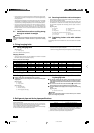
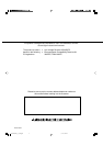
<Table 1>
System configuration For a single-refrigerant system For a multi-refrigerant system
Transmission cable length Less than 120 m More than 120 m Regardless of length
Facility example
(for noise judgment)
Types of transmission
cables
Residence or independent store
without noise
VCTF, VCTFK, CVV, CVS, VVR,
VVF, VCT or shielding wire
CVVS or CPEVS
Building, clinic, hospital or communications
station without noise supposedly generated
from inverter equipment, private power gen-
erator, high-frequency medical equipment,
radio-used communications equipment and
so on
All facilities
Shielding wire CVVS or CPEVS
Length Less than 120 m Less than 200 m
KB79H130H01_en 07.4.25, 4:33 PM11