


8
GBDFEINLPGRRUTR
CZSVHGPO
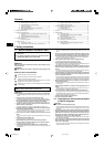
4. Fixing hanging bolts
4.1 Fixing hanging bolts
[Fig. 4.1.1] (P.2)
A Center of gravity
(Give site of suspension strong structure.)
Hanging structure
• Ceiling: The ceiling structure varies from building to one another. For detailed
information, consult your construction company.
• Do not install unit at a site where fire detector is located at the supply air side.
(Fire detector may operate erroneously due to the heated air supplied during
heating operation.)
• When special chemical product may scatter around such as site chemical plants
and hospitals, full investigation is required before installing unit. (The plastic
components may be damaged depending on the chemical product applied.)
• If the unit is run for long hours when the air above the ceiling is at high tem-
perature/high humidity (due point above 26 °C), due condensation may be
produced in the indoor unit. When operating the units in this condition, add
insulation material (10-20 mm) to the entire surface of the indoor unit to avoid
due condensation.
3.1. Install the indoor unit on a ceiling strong
enough to sustain its weight
Warning:
The unit must be securely installed on a structure that can sustain its weight.
If the unit is mounted on an unstable structure, it may fall down causing
injuries.
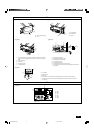
3.2. Securing installation and service space
• Select the optimum direction of supply airflow according to the configuration of
the room and the installation position.
• As the piping and wiring are connected at the bottom and side surfaces, and
the maintenance is made at the same surfaces, allow a proper space properly.
For the efficient suspension work and safety, provide a space as much as
possible.
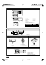
[Fig. 3.2.1] (P.2)
A Access door B Electrical parts box
C Air inlet D Air outlet
E Ceiling surface F Service space (viewed from the side)
G Service space (viewed from the direction of arrow)
1 600 mm or more 2 100 mm or more
3 10 mm or more 4 300 mm or more
3.3. Combining indoor units with outdoor
units
For combining indoor units with outdoor units, refer to the outdoor unit installation
manual.
• If necessary, reinforce the hanging bolts with anti-quake supporting members
as countermeasures against earthquakes.
* Use M10 for hanging bolts and anti-quake supporting members (field supply).
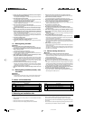
5. Installing the unit
5.1. Hanging the unit body
ss
ss
s Bring the indoor unit to an installation site as it is packed.
ss
ss
s To hang the indoor unit, use a lifting machine to lift and pass through the
hanging bolts.
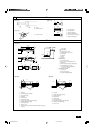
[Fig. 5.1.1] (P.2)
A Unit body
B Lifting machine
[Fig. 5.1.2] (P.2)
C Nuts (field supply)
D Washers (accessory)
E M10 hanging bolt (field supply)
5.2. Confirming the unit’s position and fix-
ing hanging bolts
ss
ss
s Use the gage supplied with the panel to confirm that the unit body and
hanging bolts are positioned in place. If they are not positioned in place,
it may result in dew drops due to wind leak. Be sure to check the positional
relationship.
ss
ss
s Use a level to check that the surface indicated by
AA
AA
A is at level. Ensure
that the hanging bolt nuts are tightened to fix the hanging bolts.
ss
ss
s To ensure that drain is discharged, be sure to hang the unit at level using
a level.
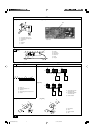
[Fig. 5.2.1] (P.2)
A Indoor unit’s bottom surface
Caution:
Install the unit in horizontal position. If the side with drain port is installed
higher, water leakage may be caused.
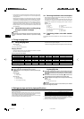
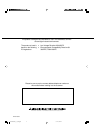
6. Refrigerant pipe and drain pipe specifications
Model name
PEFY-P15VMS1(L)-E
PEFY-P20VMS1(L)-E
PEFY-P25VMS1(L)-E
PEFY-P32VMS1(L)-E
PEFY-P40VMS1(L)-E
PEFY-P50VMS1(L)-E
PEFY-P63VMS1(L)-E
W
625
625
625
625
625
625
625
L
752
752
752
752
952
952
1152
X
263
263
263
275
280
280
285
Y
338
338
338
340
422
422
511
Z
105
105
105
104
104
104
104
Product Weight (kg)
19
19
19
20
24
24
28
Center of gravity and Product Weight
To avoid dew drops, provide sufficient antisweating and insulating work to the re-
frigerant and drain pipes.
When using commercially available refrigerant pipes, be sure to wind commer-
cially available insulating material (with a heat-resisting temperature of more than
100 °C and thickness given below) onto both liquid and gas pipes.
Insulate all indoor pipes with form polyethylene insulation with a minimum density
of 0.03 and a thickness as specified in the table below.
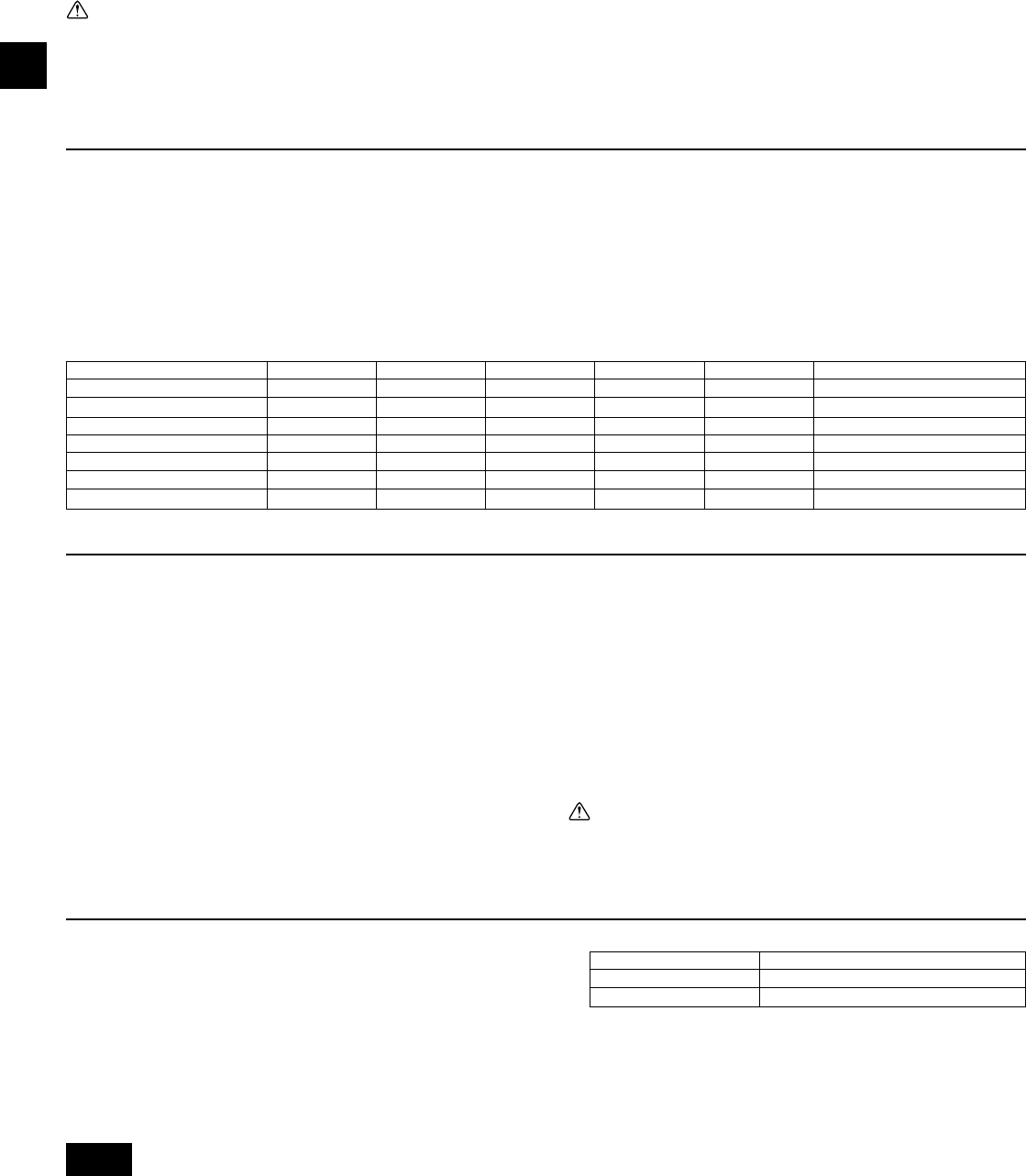
1 Select the thickness of insulating material by pipe size.
Pipe size Insulating material’s thickness
6.4 mm to 25.4 mm More than 10 mm
28.6 mm to 38.1 mm More than 15 mm
2 If the unit is used on the highest story of a building and under conditions of
high temperature and humidity, it is necessary to use pipe size and insulating
material’s thickness more than those given in the table above.
3 If there are customer’s specifications, simply follow them.
KB79H130H01_en 07.5.28, 4:08 PM8