12
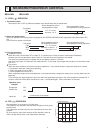
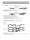
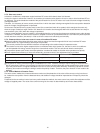
<SWING operation>
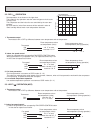
In swing operation of ECONO COOL operation mode, the initial air flow direction is adjusted to “Horizontal”.
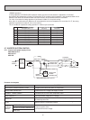
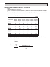
According to the temperature of indoor coil thermistor RT12 at starting of this operation, next downward blow time is
decided. Then when the downward blow has been finished, next horizontal blow time is decided.
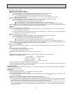
For initial 10 minutes the swing operation is performed in table G~H for quick cooling.
Also, after 10 minutes when the difference of set temperature and room temperature is more than 3.6 °F, the swing
operation is performed in table D~H for more cooling.
The air conditioner repeats the swing operation in various cycle as follows.
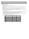
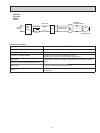
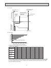
2-7. INVERTER SYSTEM CONTROL
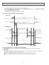
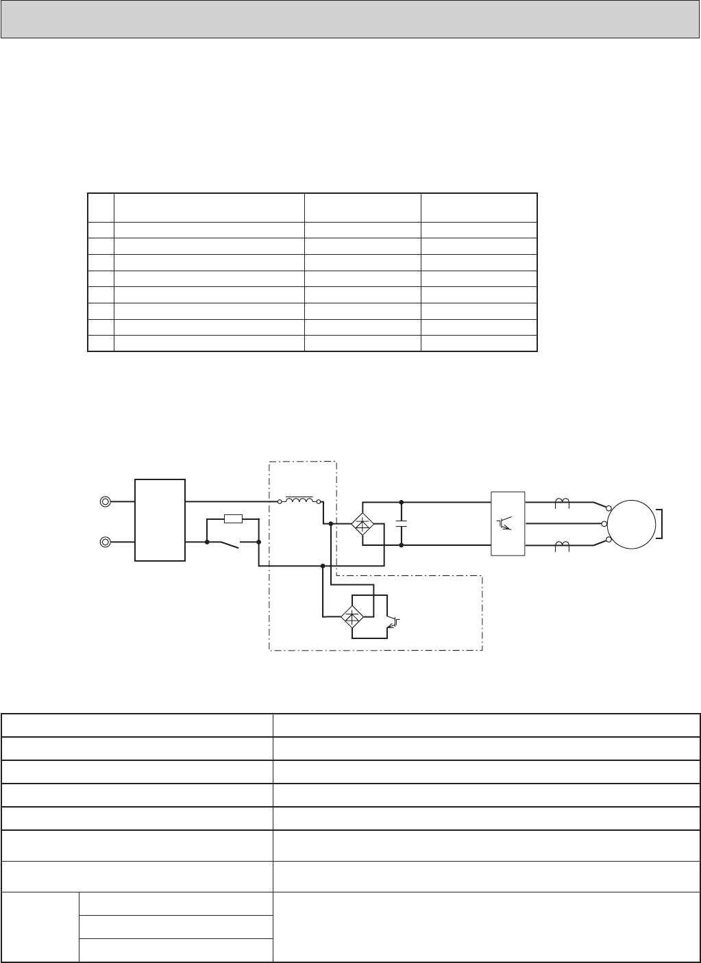
2-7-1. Inverter main power supply circuit
MUZ-A09/12/15/17
MUY-A15/17
MUZ-FD
POWER
SUPPLY
NOISE
FILTER
CIRCUIT
RESISTOR
SWITCHING
POWER
TRANSISTOR
RELAY
SMOOTHING
CAPACITOR
CURRENT
TRANSFORMER
COMPRESSOR
DIODE
MODULE1
DIODE
MODULE2
REACTOR
P
W
V
U
N
IPM
U
W
MS
3~
V
+
BOOSTER CHOPPER CIRCUIT
+
-
~~
+
-
~~
Temperature of indoor
coil thermistor (°F)
Downward blow time
(second)
Horizontal blow time
(second)
A 59 or less 2 23
B 59 to 63 5 20
C 63 to 64 8 17
D 64 to 68 11 14
E 68 to 70 14 11
F 70 to 72 17 8
G 72 to 75 20 5
H more than 75 23 2
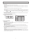
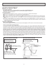
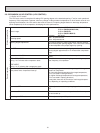
Function of main parts
NAME FUNCTION
INTELLIGENT POWER MODULE (IPM) It supplies three-phase AC power to compressor.
SMOOTHING CAPACITOR It stabilizes the DC voltage and supply it to IPM.
CURRENT TRANSFORMER It measures the current of the compressor motor.
DIODE MODULE 1 It converts the AC voltage to DC voltage.
RESISTOR
It absorbs the rush current not to run into the main power supply circuit when
the electricity turns ON.
RELAY
It short-circuits the resistance which restricts rush current during the normal
operation after the compressor startup.
BOOSTER
CHOPPER
CIRCUIT
DIODE MODULE 2
It improves power factor.
It controls the bus-bar voltage.
SWITCHING POWER TRANSISTOR
REACTOR


