


28
9-2.MSZ-A24NA MSY-A24NA
OPERATING PROCEDURE PHOTOS
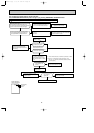
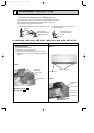
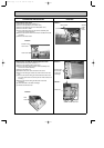
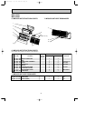
1. Removing the front panel
(1) Remove the screw caps of the front panel.
Remove the screws.
(2) Pull the panel down to your side slightly and unhook the
catches at the top.
Photo 1
Photo 2
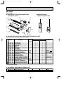
Front panel
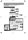
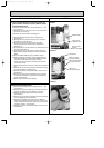
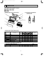
Indoor
electronic
control
P.C. board
T.B. SW cover
Screws
R.L
holder
Receiver
P.C. board
2. Removing the electronic control P.C. board, the receiver
P.C. board and the display P.C. board
(1) Remove the front panel. (Refer to 1.)
(2) Remove the corner box
(3) Remove the screw of the electrical cover.
Remove the electrical cover and T.B. SW cover.
(4) Remove the screw of the ground wire, which is solder-
mounted to the electronic control P.C. board.
(5) Remove the R.L holder.
(6) Remove the screw of the conduit cover.
(7) Remove the conduit cover.
(8) While pulling the electronic control P.C. board forward little
by little, disconnect all the connectors from the board.
(9) Remove the electronic control P.C. board.
(10) Open the R.L holder, remove the receiver P.C. board and
the display P.C. board.
Photo 3
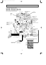
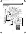
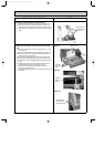
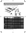
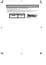
3. Removing the electrical box
(1) Remove the front panel. (Refer to 1.)
(2) Remove the electrical cover. (Refer to 2.)
(3) Disconnect the connector of the indoor coil thermistors.
(4) Disconnect the indoor fan motor connector (CN211) and
the vane motor connector (CN151 and CN152) on the
electronic control P.C. board.
(5) Remove the screw of ground wire to the heat exchanger.
(6) Remove the fan motor lead wire and indoor coil thermistor
from the electrical box.
(7) Remove the lead wire of vane motor from the bottom of
electrical box.
(8) Remove the screw fixing the electrical box and remove the
electrical box.
Screw of the
electrical box
Screw of the
ground wire
Corner box
Screw of
T.B. SW cover
Screw of the
electrical cover
Conduit cover
Screw of the ground wire
Screw of
conduit cover
OB450B-1.qxp 07.5.14 4:14 PM Page 28