13
4. Intelligent power module
IPM consists of the following components
· IGBT (x6) : Converts DC waveform to three-phase AC waveform and outputs it.
· Drive Circuit : Drives transistors.
· Protection circuit : Protects transistors from overcurrent.
Since the above components are all integrated in IPM, IPM has a merit to make the control circuit simplify and miniaturize.
5. Smoothing capacitor
C63A, C63B and C63C stabilize the DC voltage and supply it to IPM.
6. Elimination of electrical noise
Noise filter circuit, which is formed by *CMC COILS capacitors placed on the POWER P.C. board, eliminates electrical
noise of AC power that is supplied to main power supply circuit. And this circuit prevents the electrical noise generated in
the inverter circuit from leaking out.
*CMC COILS; Common mode choke coils
Outline of simple partial switching method
In conventional inverter models, diode module rectifies AC voltage to DC voltage, smoothing capacitor makes its DC waveform
smooth, and IPM converts its DC voltage to imitated AC voltage again in order to drive the compressor motor.
However, it has been difficult to meet IEC harmonic current emission standard by above circuit because harmonic gets
generated in the input current waveform and power factor gets down. The simple partial switching method with PAM, which has
been adopted this time, places and utilizes the booster chopper circuit (L61, DB65 and TR821) before rectifying AC voltage in
the general passive-method converter circuit. As harmonic gets suppressed and the peak of waveform gets lower by adding
booster chopper circuit as mentioned above and by synchronizing the timing of one-time switching with the zero-cross point of
waveform, the input current waveform can be improved and the requirement of IEC harmonic current emission standard can be
satisfied. Since the switching times is just once by synchronizing with the zero cross point, this simple partial switching method
has the feature of lower energy loss compared to active filter method. In addition, output and efficiency is enhanced by
combining with vector-controlled inverter in order to boost the voltage of power supplied to IPM.
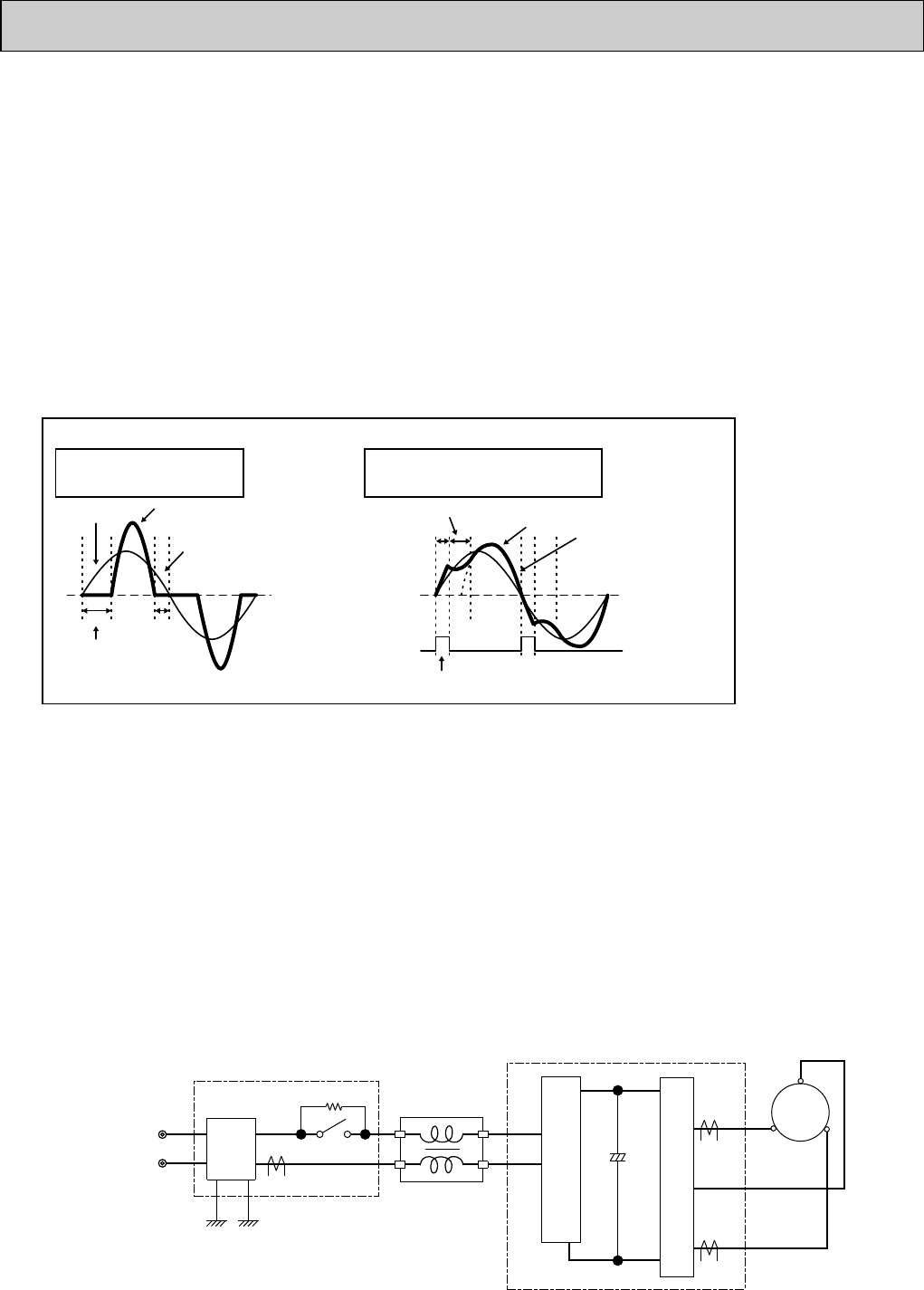
Input current waveform without PAM Input current waveform with PAM
Due to the time of no electricity;
· Power factor gets worse.
· Harmonic gets increased.
Input voltage
Release of energy stored in L
Energized time is
extended by optimization
of L inductance.
Peak gets down.
Energized time is short in
case L inductance is small.
No electricity runs into
diode module because the
voltage at both sides of smoothing
capacitor is higher than input voltage.
Compulsory energizing
by switching.
Input current
Owing to the increase of energized time;
· Power factor gets better.
· Harmonic gets suppressed.
3. Purpose of PAM adoption
PAM : Pulse Amplitude Modulation
PAM has been adopted for the efficiency improvement and the adaptation to IEC harmonic current emission standard.
2-7-2. MUZ-A24
MUY-A24
2-7-2-1. Inverter main power supply circuit
W
MC
V
U
W
V
U
IPM
CB3
CB2
+CB1
PFC
CT61
N/F
CT2
CT1
X64
R64A/R64B
L
POWER
SUPPLY
POWER BOARD
P. C. BOARD
FILTERNOISE
OBT16--1.qxp 06.3.29 11:20 AM Page 13


