


21
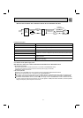
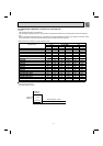
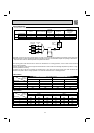
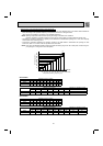
3-1. INVERTER SYSTEM CONTROL
POWER
SUPPLY
NOISE
FILTER
CIRCUIT
RESISTOR
RELAY
SMOOTHING
CAPACITOR
CURRENT
TRANSFORMER
COMPRESSOR
REACTOR
P
W
V
U
N
IPM
PFC
U
W
MS
3~
V
+
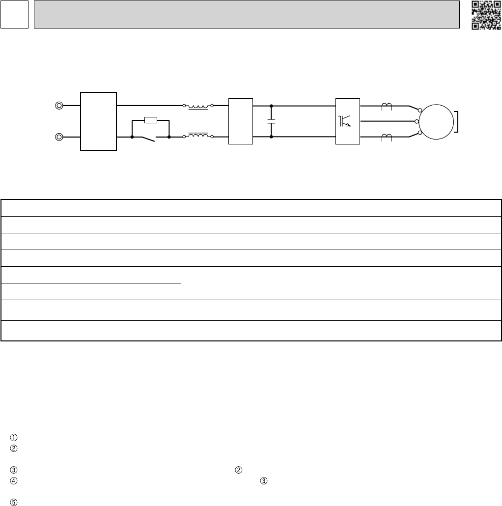
3-1-1. Inverter main power supply circuit
Function of main parts
NAME FUNCTION
INTELLIGENT POWER MODULE (IPM) It supplies 3-phase AC power to compressor.
SMOOTHING CAPACITOR It stabilizes the DC voltage and supplies it to IPM.
CURRENT TRANSFORMER It measures the current of the compressor motor.
REACTOR
It rectifi es AC, controls its voltage and improves the power factor of power supply.
POWER FACTOR CORRECTION MODULE (PFC)
RESISTOR
It absorbs the rush current not to run into the main power supply circuit when the
electricity turns ON.
RELAY
It keeps the RESISTOR, which restricts rush current, short-circuited while the
compressor is operating.
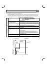
3-1-2. Outline of main power supply circuit
1. At the start of operation
Main power supply circuit is formed when RELAY is turned ON at COMPRESSOR startup.
To prevent rush current from running into the circuit when power supply is turned ON, RESISTOR is placed in sub circuit.
2. At normal operation
When AC runs into noise fi lter P.C. board, its external noise is eliminated in NOISE FILTER CIRCUIT.
After noise is eliminated from AC, it is rectifi ed to DC by REACTOR and PFC. If the operating frequency becomes 25 Hz or
more, DC voltage rises to 370 V.
DC voltage, to which has AC been rectifi ed by process , is stabilized by SMOOTHING CAPACITOR and supplied to IPM.
The DC (Bus voltage), which has been stabilized in process , is converted to 3-phase AC by IPM and supplied to COM-
PRESSOR.
CURRENT TRANSFORMER, which is placed in the power supply circuit to COMPRESSOR, is used to measure the value
of phase current and locate the polar direction of rotor with algorithm. PWM (Pulse width modulation) controls impressed
voltage and frequency with those pieces of information.
3
MXZ MICROPROCESSOR CONTROL