45
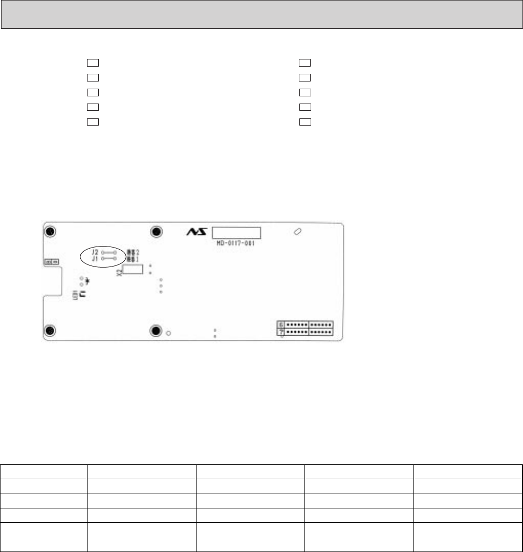
How to modify the remote controller P.C. board
Remove batteries before modification.
The board has a print as shown below :
The P.C.board has the print “J1” and “J2”.Jumper wires are mounted to each “J1” and “J2”.Cut J1 and J2 according to the
number of indoor unit as shown in Table 1.
After modification,push the reset button.
NOTE : For remodeling, take out the
batteries at first.
After finish remodeling, put
back the batteries then
push the RESET button.
No. 1 unit
No. 2 unit
No. 3 unit
No. 4 unit
1 unit operation
No modification
–
–
–
2 units operation
Same as at left
Cut J1
–
–
3 units operation
Same as at left
Same as at left
Cut J2
–
4 units operation
Same as at left
Same as at left
Same as at left
Cut both J1 and J2
Table.1
(2)<The reset button can be located on the front side.>
MSH-07NV - (Serial number 7000201T~) MSH-09NV - (Serial number 7000201T~)
MSH-12NV - (Serial number 7000001T~) MSH-24NV -
MSH-07NV - MSH-09NV -
MSH-12NV - MSH-18NV - (Serial number 7000001T~)
MSH-24NV - MSH-18NV -
E3E2
E2E2
E2E2
E1E1
E1E1
NOTE : At power supply failure or installation, indoor unit deletes the memory about remote controller. When
the power supply is turned on and indoor unit receives the first signals from the remote controller, the
remote controller number is designated as the indoor unit number. Therefore at and after the second
time indoor unit accepts the remote controller of the initial setting number.
At setting - error, turn the power supply off to cancel the individual operation and then turn the power
supply on to restart the setting.
OB207t-2qxp 25/9/97 8:55 PM Page 45


