


HEAD OFFICE
HIMEJI WORKS
: TOKYO BUILDING, 2-7-3 MARUNOUCHI, CHIYODA-KU, TOKYO 100-8310, JAPAN
: 840, CHIYODA CHO, HIMEJI, JAPAN
Warranty
Mitsubishi will not be held liable for damage caused by factors found not to be the cause of Mitsubishi;
opportunity loss or lost profits caused by faults in the Mitsubishi products; damage, secondary damage,
accident compensation caused by special factors unpredictable by Mitsubishi; damages to products
other than Mitsubishi products; and to other duties.
For the detailed warranty, refer to the GOT-F900 Series HARDWARE MANUAL [CONNECTION].
2.2 Power Supply Specifications
2.3 Screen Hardware Specifications
• Bright dots (always lit) and dark dots (unlit) may appear on a liquid crystal display panel. It is
impossible to completely avoid this symptom, as the liquid crystal display comprises of a great
number of display elements.
Flickers may be observed depending on the display color.
Please note that these dots appear due to its characteristic and are not caused by product defect.
• When the same screen is displayed for a long time, an incidental color or partial discoloration is
generated on the screen due to heat damage, and it may not disappear.
• Using the GOT Backlight OFF function can prolong the life of the backlight.
For details on the Backlight OFF function, refer to the following.
GOT-F900 Series OPERATION MANUAL/GOT-F900 Series OPERATION MANUAL [GT Designer2
Version]
3. Installation
Note;
• Do not mount the GOT in an environment that contains dust, soot corrosive or conducive
dust, corrosive or flammable gas, or expose the unit to high temperatures, dew
condensation, direct sunlight, rain wind or impact and vibration.
If the GOT is used in such a place, electrical shock, fire, malfunction, damages or
deterioration may caused.
• Never drop cutting chips or electric wire chips into the ventilation window of the GOT
when drilling screw holes or performing wiring. Such chips may cause fire, failure or
malfunction.
• Turn off the power before securely connecting any cables. Poor connection may cause
malfunction.
The GOT is designed to be mounted in a panel. Install it using the following procedure:
1) Preparing the panel surface.
On the panel surface, cut a rectangular mounting slot of the
dimensions shown on the right.
At this time, space of 10 mm is required at each of the top and the
bottom of the slot, inside the panel for metal fixtures as shown in
“4) Dimensions required inside the panel for installation”.
Items Specifications
Power Supply Voltage 24V DC, +10% -15%
Power Supply Ripple 200 mV or less
Current Consumption
Ratings: 650 mA at 24V DC
750 mA at 24V DC or less when power supply is turned ON
400 mA at 24 V DC when backlight is turned OFF
Fuse Fuse built-in GOT (impossible to change)
Max. Allowable Momentary
Power Supply Failure period
1 ms; If less than 1 ms, the GOT will continue operation. If 1 ms or
more, the GOT will shut down.
Battery Built-in, PM-20BL type lithium battery. (Approximately 5 years life)
Items Specifications
Display Device TFT colour liquid crystal
Resolution 480
×
234 (dot), 60 characters
×
14 lines
Dot Pitch
0.324 mm (0.013") Horizontal
×
0.375 mm (0.015") Vertical.
[Actual character size ratio 1:1.16]
Effective Display Size 155.5 mm (6.12")
×
87.8 mm (3.46"); 7 (inch) type
Number of Colours 256 colours
Life of liquid crystal
50,000 hours or more
(Operating temperature: 25
°
C / 77
°
F)
Backlight Cold cathode tube
Life of Backlight
50,000 hours or more
(Operating temperature: 25
°
C / 77
°
F)
Touch Keys Maximum 50 touch keys / screen, 30
×
12 matrix
Interface
COM0 RS-422
COM1 RS-232C
COM2 RS-232C
Number of Screens
User screen: 500 screens or less
System screen: Allocated screens No. 1001-1030.
User Memory Flash memory 1MB (built-in)
S lo t to b e c u t o n p a n e l
2 0 6 ( 8 .1 1 " )
+ 1 ( + 0 .0 4 " )
0
U n it: m m ( in c h e s )
1 2 4
( 4 .8 8 " )
+ 1 ( + 0 .0 4 " )
0
Note
• Make sure that the thickness of the panel surface is no more than 5 mm (0.20").
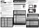
2) Inserting the GOT into the panel surface
Attach the packing seal to the GOT, and insert the GOT from
the front face of the panel surface.
a) Packing seal
b) GOT
c) Mounting slot
3) Fixing the GOT
Put hooks of the mounting brackets (supplied) in to the
mounting holes of the GOT. Tighten mounting bolts (also
supplied) until the GOT is securely fixed.
Fix mounting bolts in all four positions, above and below the
GOT.
a) Clamping bolt
b) Mounting bracket
Note:
Make sure to tighten the clamping bolts with a torque of 0.3 ~ 0.5 N
m.
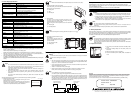
4) Dimensions required inside the panel
for installation.
When installing the GOT, make sure
that the inner dimensions shown on the
right are available.
a) PLC connection cable
b) Packing seal
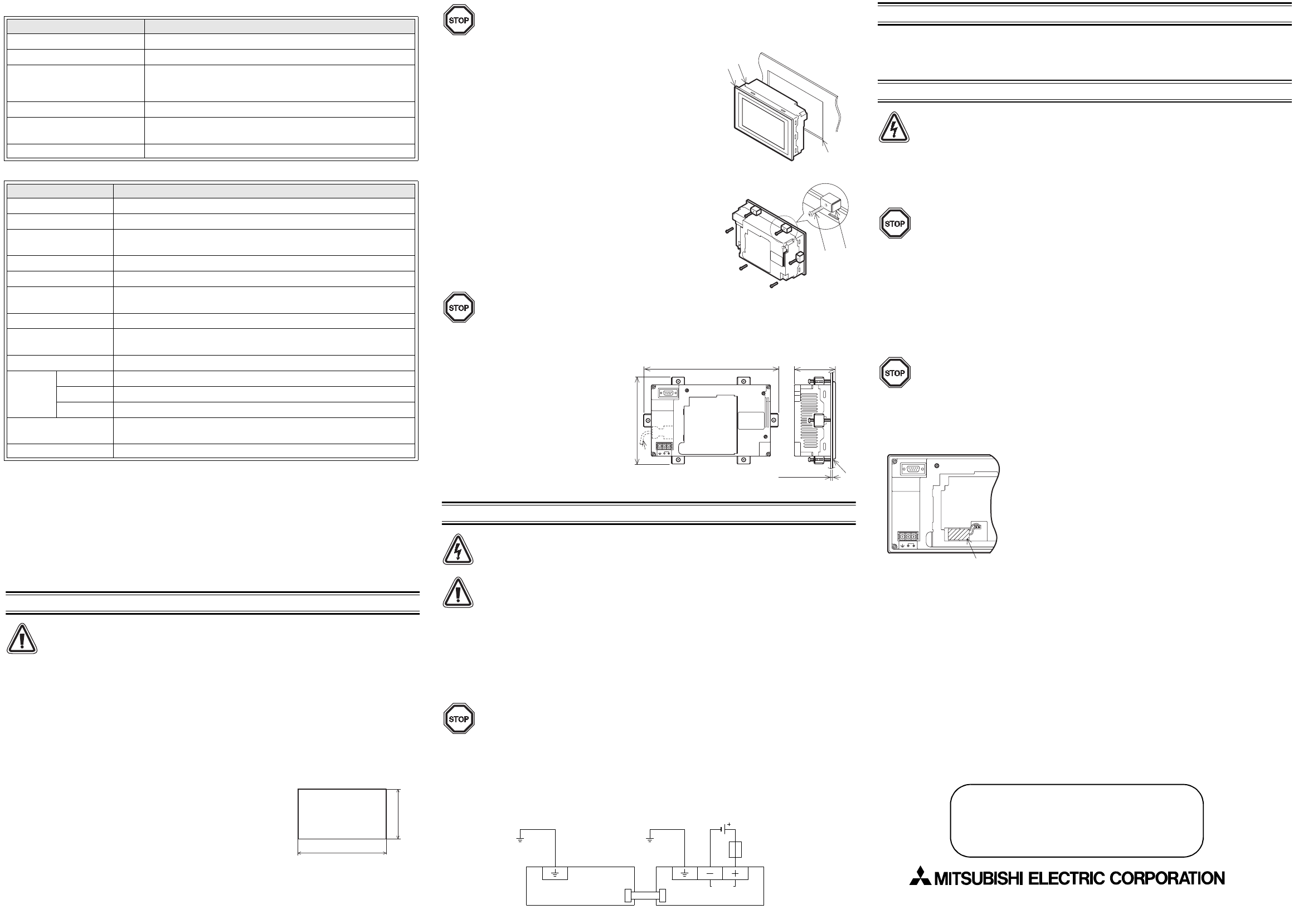
4. Power Supply Wiring
Caution:
Cut OFF all external phases of power source, before installation or wiring to avoid electric
shock or serious damage to the product.
Note:
• Wire the power supply using electric wires of 0.75 mm
2
or more so that voltage drop will
not occur. Use M3 size crimp style terminals. Securely tighten crimp-style terminals with a
torque of 0.5 ~ 0.8 N
m so that errors can be avoided.
• Insure correct termination of the DC power source, incorrect connection may result in unit
failure serious damage to the GOT.
• Attach a 2 A fuse to the 24V DC power supply.
• Perform Class D (100
Ω
or less) grounding with an electric wire of at least 1.25 mm
2
.
Never perform common grounding of the GOT and a strong power system.
Note
• Use an external power supply to provide 24V DC.
(The service power supply of the programmable controller cannot be used.)
• Even if instantaneous power interruption of less than 1 ms occurs, the GOT continues to
operate. When power interruption for a considerable period of time or voltage drop occurs,
the GOT stops its operation. However, when the power supply is recovered, the GOT
automatically restarts its operation. (The screen displayed just after recovery is
determined by the working environment originally set.)
b )
a )
c )
b )
a )
5 ( 0 .2 0 " ) o r le s s
7 0 .6 ( 2 . 7 8
"
)
b )
2 2 5 ( 8 .8 6 " )
1 4 3 ( 5 .6 3 " )
a )
PLC GOT
24V DC
Fuse (2A)
24V DC external
power supply
Grounding resistance
100
Ω
or less (class D)
5. Expansion Module (F9GT-40FMB)
F9GT-40FMB has a built-in flash memory and can transfer screen data when installed in the GOT.
(When installed in the OS earlier than version 1.40, screen display is not available while transferring data
from F9GT-40FMB to the GOT.)
For the use methods and specifications, refer to the manual for F9GT-40FMB.
6. Maintenance
Cautions:
• Correctly connect the battery for memory backup. Never charge, disassemble, heat, burn
or short-circuit the battery. If the battery is handled in such a way, or fire may be caused.
• Always power OFF and remove the GOT from the panel before starting replacement of
the battery. If this is not the case, electrical shock may be sustained.
• Never disassemble or modify the GOT. Disassembly or modification may cause failure,
malfunction or fire. For repair, please, contact a service representative.
Note:
Turn off the power, before connecting/disconnecting cables.
Connecting/disconnecting cables while the power is turned on will cause failure or
malfunction.
When repairing the backlight and liquid crystal screen, please, contact a service representative.
6.1 Battery Replacement
When the battery voltage drops, a control device (system information) set by the screen design software
turns ON. The control device interlocks with an auxiliary relay in the PLC. It is recommended to provide a
lamp while utilizing the output of the PLC so that voltage drop can be monitored outside the GOT.
For details of control devices, refer to the GOT-F900 Series Operation Manual.
Note:
For approximately one month after the control device (system information) for battery voltage
drop turns ON, the battery will back up the alarm history, sampling and the current time. When
the control device turns ON, replace the battery (PM-20BL) as soon as possible.
The screen data is stored in the flash memory, therefore, data will remain even after severe
battery voltage loss.
6.1.1 Replacement Procedure
1) Turn off the power to the GOT and remove the battery holder
cover.
2) Remove the existing battery from the battery holder, and
disconnect.
3) Within 30 seconds, connect a new battery.
4) Insert the new battery into the battery holder, and attach the
cover.
P M - 2 0 B L
Manual number: JY992D93901
Manual revision: E
Date : Sep. 2008