


HEAD OFFICE
HIMEJI WORKS
: TOKYO BUILDING, 2-7-3 MARUNOUCHI, CHIYODA-KU, TOKYO 100-8310, JAPAN
: 840, CHIYODA CHO, HIMEJI, JAPAN
Warranty
Mitsubishi will not be held liable for damage caused by factors found not to be the cause of Mitsubishi;
opportunity loss or lost profits caused by faults in the Mitsubishi products; damage, secondary damage,
accident compensation caused by special factors unpredictable by Mitsubishi; damages to products
other than Mitsubishi products; and to other duties.
For the detailed warranty, refer to the GOT-F900 Series HARDWARE MANUAL [CONNECTION].
2.3 Screen Hardware Specifications (F920GOT-BBD5-K-E and F920GOT-BBD-K-E)
• Bright dots (always lit) and dark dots (unlit) may appear on a liquid crystal display panel. It is
impossible to completely avoid this symptom, as the liquid crystal display comprises of a great
number of display elements.
Flickers may be observed depending on the display color.
Please note that these dots appear due to its characteristic and are not caused by product defect.
• When the same screen is displayed for a long time, an incidental color or partial discoloration is
generated on the screen due to heat damage, and it may not disappear.
3. Installation
Note
• Do not mount the GOT in an environment that contains dust, corrosive soot, conducive dust, corrosive
or flammable gas, or expose the unit to high temperatures, dew condensation, direct sunlight, rain and
wind or impact and vibration.
If the GOT is used in such a place, electrical shock, fire, malfunction, damages or deterioration may
occur.
• Never drop cutting chips or electric wire chips into the ventilation window of the GOT when drilling
screw holes or performing wiring. Such chips may cause fire, failure or malfunction.
• Make sure that the power is turned off, before securely connecting any cables. Poor connection may
cause malfunction.
The GOT is designed to be mounted in a panel. Install it using the following procedure:
The installation method and the dimensions required inside the panel are identical for the F920GOT-BBD5-K-E and
F920GOT-BBD-K-E.
Illustrations of the F920GOT-BBD-K are used in the explanation for this manual.
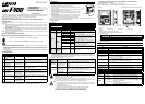
1) Preparing the panel surface.
(See Figure A)
On the panel surface, cut a rectangular mounting slot with the dimensions shown below.
A space of 10 mm is required for the right and left sides of the slot and inside the panel for metal fixtures as shown in
“5) Inner panel installation dimensions”.
Note
Make sure that the thickness of the panel surface is no more than 5 mm (0.20").
2) Inserting the GOT into the panel surface
(See Figure B)
Attach the packing seal to the GOT, and insert the GOT from the front face of the panel surface.
a) Packing seal
b) GOT
c) Mounting slot
3) Fixing the GOT
(See Figure C)
Attach the hooks of the mounting brackets (supplied) in to the mounting holes of the GOT. Tighten mounting bolts
(also supplied) until the GOT is securely fixed.
Fix mounting bolts in all four positions, right and left of the GOT.
a) Clamping bolt
b) Mounting bracket
Note
Tighten the clamping bolts with a torque of 0.18 to 0.22 N
m.
4) Peeling of the protective sheet
Peel off the protective sheet on the surface of the product before use.
5) Inner panel installation dimensions
(See figure D)
.
When installing the GOT, make sure the inner dimensions shown below are available.
a) PLC connection cable
b) Packing seal
Items Specifications
Display Device STN monochrome liquid crystal display
Resolution 128
×
64 (dot), 16 characters
×
4 lines
Dot Pitch 0.47 mm (0.019") Horizontal
×
0.47 mm (0.019") Vertical.
Effective Display Size 60 mm (2.36")
×
30 mm (1.18") 3(2.64" inch) type
Number of Colors 2 colors (White and Blue)
Life of liquid crystal display Approximately 50,000 hours (Operating temperature: 25
°
C/77
°
F)
Backlight LED (White and Red)
Keypad 26 keys (0 to 9 keys, Cursor keys, Function keys, SET key, DEV key, ESC key, ENT key)
Interface
RS-422 RS-422 (COM0)
RS-232C RS-232C (COM1)
Number of Screens
User screen: 500 screens or less
System screen: Allocated screens No. 1001-1030.
User Memory Flash memory 128 KB (built-in)
24VDC
a)
b)
C
92(3.62")
+1(+0.04")
0
Slot to be
cut on panel
119(4.69")
Unit: mm(inches)
+1(+0.04")
0
A
c)
a)
b)
B
4. Power Supply Wiring (F920GOT-BBD-K-E)
Cautions
• Cut OFF all external phases of the power supply before installation or wiring to avoid electric shock or
serious damage to the product.
Note
• Wire the DC power supply to the dedicated terminals as described in this manual. Wiring an AC power
supply will cause serious damage to the product.
• Attach a 2A fuse to the 24V DC power supply. Correctly connect the + and - terminals of the DC power
supply as descried in this manual.
Reverse connection of the power supply may cause failure.
• Perform grounding (resistance: 100
Ω
or less) with an electric wire of 1.25 mm
2
or more to the ground
terminal of the GOT.
Never perform common grounding of the GOT and a strong power system.
The power for the F920GOT-BBD-K-E is externally supplied through the power terminals provided on the rear face.
(The power for the F920GOT-BBD5-K-E is supplied from the PLC through a communication cable.)
The power of the GOT is supplied from the PLC or an external power supply.
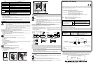
• Connection example
Crimp-style terminal When wiring 1 wire per terminal When wiring 2 wires per terminal
Cautions on connection
The current consumption of the GOT is 80mA/24V DC (while the backlight is ON). When supplying power from the 24V
DC service power supply of the FX Series PLC main unit or extension unit, consider the capacity of the service power
supply of the base or extension unit and the total current supplied to proximity switches, extension blocks and special
blocks. If the total current including the power supplied to the GOT exceeds the capacity of the service power supply,
supply the power to the GOT from the external power supply.
• Even if instantaneous power interruption of less than 5 ms occurs, the GOT continues to operate. When power
interruption for a considerable period of time or voltage drop occurs, the GOT stops its operation. However, when the
power supply is recovered, the GOT automatically restarts its operation. (The screen displayed just after recovery is
determined by the working environment originally set.)
• When wiring the power supply, use electric wires of 0.75 mm
2
or more to avoid voltage drop. Use crimp-style
terminals for M3, and securely tighten them with a tightening torque of 0.5 to 0.8 N·m to avoid troubles.
5. Maintenance
Cautions
Never disassemble or modify the GOT. Disassembly or modification may cause failure, malfunction or fire.
For repair, please, contact a service representative.
Note
Make sure to turn OFF the power, before connecting/disconnecting cables.
If you connect/disconnect cables while the power is turned on, failure or malfunction may be caused.
A backlight lithium battery is not supplied with the GOT. The Liquid Crystal Display has a service life of approximately
50,000 hours.
When repairing the Liquid Crystal Display, please, contact a service representative.
134(5.28")
70(2.76")
7(0.28")
10
(0.39")
5(0.20")
86(3.39")
7(0.28")
10(0.39")
5(0.20")
10(0.39")
86(3.39")
99(3.90")
109(4.29")
5(0.20") or less
35.5(1.40")
5(0.20")
10
(0.39")
(cable)
10(0.39")
b)
a)
Unit: mm(inches)
COM1 RS232C
COM0 RS422
D
24VDC
1) When supplying the power from the FX Series PLC
Connect the power terminals provided on the rear face
of the GOT to the 24V DC service power supply of the
PLC base or extension unit.
2) When supplying the power from an external power
supply
Connect the power terminals provided on the rear face
of the GOT to the 24V DC terminals of the external
power supply.
PLC GOT
24+ COM - +
24V
DC
2A
Grounding
resistance
100
Ω
or less
PLC GOT
24+ COM - +
24V
DC
2A
External
power
supply
Grounding
resistance
100
Ω
or less
Grounding
resistance
100
Ω
or less
Crimp-style
terminal
Terminal
screw
Terminal
C
r
i
mp-sty
l
e
terminal
T
erm
i
na
l
screw
Terminal
6.2 mm(0.24")
or less
φ
3.2(0.13")
6.2 mm (0.24")
or less
φ
3.2(0.13")
Notification of CE marking
The following products have shown compliance through direct testing (to the identified standards) and design analysis
(forming a technical construction file) to the European Directive for Electromagnetic Compatibility (2004/108/EC) when
used as directed by the appropriate documentation.
• This product is designed for use in industrial applications.
• Manufactured by:Mitsubishi Electric Corporation
2-7-3 Marunouchi, Chiyoda-ku, Tokyo 100-8310 Japan
• Manufactured at: Mitsubishi Electric Corporation Himeji Works
840 Chiyoda-machi, Himeji, Hyogo 670-8677 Japan
• Authorized Representative in the European Community: Mitsubishi Electric Europe B.V.
Gothaer Str. 8, 40880 Ratingen, Germany
Type : Programmable Controller (Open Type Equipment)
Models : MELSEC GOT series products, identified here, manufactured from
December 1st, 2009 F920GOT-BBD5-K-E
F920GOT-BBD-K-E
For more details please contact the local Mitsubishi Electric sales site.
Notes Regarding the Use of GOT Units
General notes on the use of Communication Cables
Any device which utilizes a data communication function is susceptible to the wider effects of local EMC noise. Therefore,
when installing any communication cables care should always be taken with the routing and location of those cables. The
GOT units identified on the previous page are compliant with the EMC requirement when the following communication
cables are used:
When using the FX-50DU-CAB0/EN cable the Earth Strap must be connected to a suitable earth point.
Ex. 1
E = Additional earth strap connected to the cables shield. Free end of the earth strap must be connected to an earth
point.
F = Ferrite core
Ex. Tokin - ESD-R-17S or similar
Standard Remark
EN61131-2 : 2007
Programmable controllers
- Equipment, requirement and tests
EMI
Compliance with all relevant aspects of the standard.
(Radiated Emissions)
EMS
Compliance with all relevant aspects of the standard.
(ESD, RF electromagnetic field, EFTB, Surge, RF conducted
disturbances and Power frequency magnetic field)
GOT Units Existing Cables User Made Cables
F920GOT-BBD5-K-E
F920GOT-BBD-K-E
FX-50DU-CAB0/EN
and
FX-50DU-CAB0 modified as
shown in EX.1
This cable need to be independently tested by the
user to demonstrate EMC compatibility when they
are used with Mitsubishi GOT units and
Programmable Controllers.
E
F F F
FX-50DU-CAB0
110 (4.33")
GOT units
Programmable
Controller
Unit: mm (inches)
Manual number: JY997D02201
Manual revision: G
Date : Aug. 2010