530.70-N1.11Y
Unitary Products Group 5
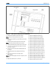
31. Attach wire 816/R from MR-7 to 8T-2.
32. Attach wire 201/R from 8T-1 to 30FU.
33. Attach wire 204/BR to the new location on 8T-2.
34. Attach wire 257/Y from APS-N0 to CR1-7.
35. Attach wire 817/Y from CR1-7 to CR2-7.
36. Attach wire 818/Y from CR2-7 to CR3-7.
37. Attach wire 819/Y from CR3-7 to CR4-7.
NOTE:
IF UNIT HAS OPTIONAL HEAT PLEASE CONTINUE
WITH STEP 38.
UNITS W/O ECONOMIZER AND OPTIONAL GAS OR
ELECTRIC HEAT
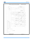
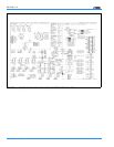
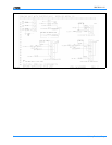
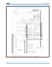
Units with optional Gas or Electric heat should follow the
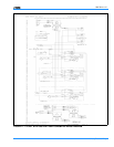
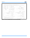
steps below. See Figure 7 for Gas Heat and Figure 8 for
Electric Heat.
NOTE:
This wire will be used with the new controls.
38. Mount WR1 & WR2 relays in the heat section.
39. Attach wire 526/R to the new location on 8T-7.
40. Attach wire 845/W from TB12-W1 to WR1-A.
41. Attach wire 844/GY from TB12-W2 to WR2-A
1
.
42. Attach wire 820/Y from CR4-7 to WR1-7.
43. Attach wire 823/Y from WR1-7 to WR2-7
1
.
44. Attach wire 826/BR from WR1-B to WR2-B
1
.
45. Attach wire 822/BR from WR1-B to TB2.
46. Attach wire 512/W to the new location at WR1-5.
47. Attach wire 510/GY to the new location at WR2-5
1
.
48. Attach wire 533/GY to the new location on TB12-G.
END OF INSTALLATION FOR CV UNIT WITHOUT ECONO-
MIZER.
1. Only on units with 480 and 780 MBH gas unit or with
80kW and 180kW electric heat.


