530.70-N1.11Y
4 Unitary Products Group
5. Disconnect wire 526/R from the 30FU location.
NOTE:
This wire will be used with the new controls.
6. Disconnect wire 533/GY from the W7400 control module
G terminal.
7. Disconnect wires 510/GY and 512/w from W1 & W2.
NOTE: These wires will be used with the new controls.
8. Remove the W7400 control module from the control box.
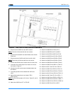
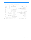
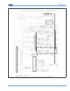
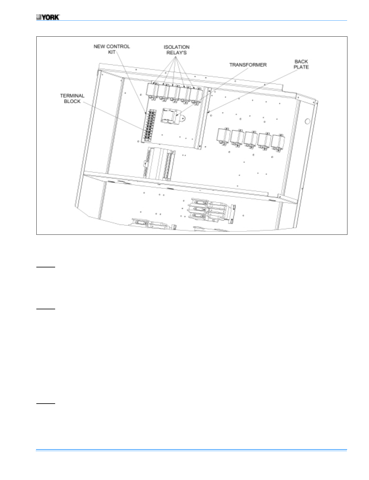
9. Locate the new control plate in box-electric in the loca-
tion shown in Figure 4.
10. Using the four drill screws secure the back plate to the
box-electric.
11. Locate the packet of wires marked with “No Econo-
mizer”.
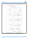
12. Attach thermostat wires to new location TB12
(See Figure 3).
NOTE:
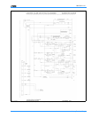
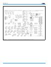
For the following steps (13-34) see Figures 5, and 6
respectively.
13. Attach wire 230/R from 8T-7 to TB12-R .
14. Attach wire 836/BR from TB2 to 8T-6.
15. Attach wire 842/BR from 8T-6 to MR-B.
16. Attach wire 814/BR from MR-B to CR1-B.
17. Attach wire 813/BR from CR1-B to CR2-B.
18. Attach wire 812/BR from CR2-B to CR3-B.
19. Attach wire 834/BR from CR3-B to CR4-B.
20. Attach wire 835/BR from CR4-B to TB12-C.
21. Attach wire 800/GY from MR-A to TB12-G.
22. Attach wire 801/Y from CR1-A to TB12-Y1.
23. Attach wire 802/O from CR2-A to TB12-Y2.
24. Attach wire 803/PR from CR3-A to TB12-Y3.
25. Attach wire 821/GY from CR4-A to TB12-Y4.
26. Attach wire 240/Y from CR1-5 to LOR1-1-7.
27. Attach wire 244/O from CR2-5 to LOR1-2-9.
28. Attach wire 839/PR from CR3-5 to LOR2-1-7.
29. Attach wire 248/GY from CR4-5 to LOR2-2-9.
30. Attach wire 252/R from CL01 to MR-7.
FIGURE 4 : NEW LOW VOLTAGE CONTROL COMPONETS


