


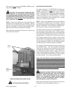
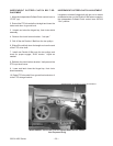

CLEAN-OUT PANEL
Remove clean-out panel on a regular basis to clean out
accumulation of foreign materialbuild-up. Keep this area
clean for proper cross conveyor chain operation.
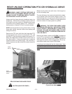
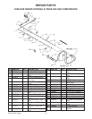
CROSS CONVEYOR CHAIN
WITH CROSS APRON HOLD DOWNS
Correct adjustment of the cross apron chain occurs
when 12" of chain, APRON SLAT does not touch the
BOTTOM PAN of the cross apron return area at the dis
-
charge opening. To tighten the chain, loosen the two
bolts securing the slotted bearing bracket at each side of
the discharge opening. Tighten the chain by tightening
the nut on the adjuster bolt. Adjust both sides equally.
Retighten the bearing bracket bolts.
MAIN APRON CHAINS
After unloading the first ten loads from the front and also af-
ter unloading the first ten loads from the rear check the main
apron chain tension. After initial adjustment check chain
tension daily for the next five days of operation. Initial wear
in of chain will require adjustment to maintain proper chain
tension. FAILURE TO MAINTAIN PROPER CHAIN TEN-
SION MAY VOID WARRANTY. Removable master links
are included in each of the four strands for tightening after
tightener travel is at its maximum. Remove a link from each
of the fourstrands at the sametime to assure proper timing.
The main aprons are each independently tensioned by
an anchoring, adjustable bolt and pivoting arm tightener
system.
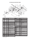
PRIOR TO 08 SERIAL NUMBERS-To tighten the main
aprons, tighten down the anchoring eye bolts centrally
located at each
side of the forage box on the steel 10”
stringers.
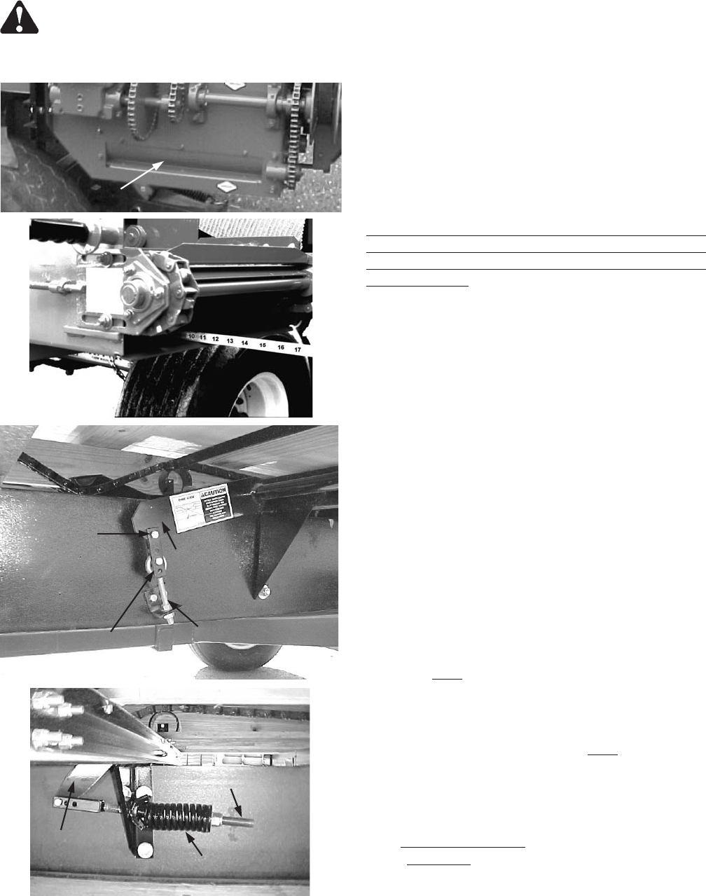
08 SERIAL NUMBERS AND LATER-To tighten the
main aprons, tighten the tensioner rod on the spring
loaded tensioner centrally located at each
side of the for
-
age box on the steel 10” stringers. Tighten the spring to
a 5” compressed length.
In addition to tightening the anchoring eye bolts, there is
located on the inner chain strands of each apron assem
-
bly a fine adjustment bolt
on the pivoting arm tightener.
Adjust as needed
to equalize stretch in chain strand pairs
of each independent apron assembly. See page 26.
3200 & 4200 Series -- 25 –
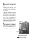
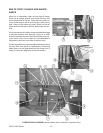
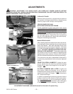
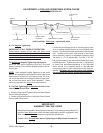
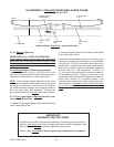
ADJUSTMENT DIAGRAMS (Shields Removed for Illustration Purposes Only)
ADJUSTMENTS
WARNING: DISCONNECT PTO DRIVE SHAFT (OR HYDRAULIC POWER SOURCE) BEFORE
CLEANING, ADJUSTING, LUBRICATING OR SERVICINGTHIS MACHINE. FAILURE TO HEED MAY RESULT IN
SERIOUS PERSONAL INJURY OR DEATH.
PIVOT ARM
PIVOT BOLT
SHACKLE BRACKET
ANCHORING EYEBOLT
PRIOR TO 08 SERIAL #’S
CLEAN OUT PANEL
PIVOT ARM
TENSIONER ROD
SPRING
08 SERIAL #’S & LATER