


NOTE: DIAGRAMS & ILLUSTRATIONS NOT TO SCALE.
3
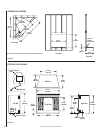
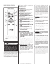
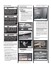
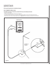
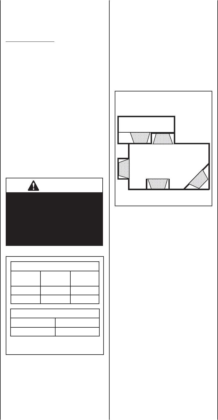
Figure 1
TOOLS AND BUILDING SUPPLIES
NORMALLY REQUIRED
Tools:
Phillips Screwdriver
7/16" Socket Drive
Hammer
Saw And/or Saber Saw
Level
Measuring Tape
Plumb Line
Electric Drill And Bits
Pliers
Square
Gloves
Building Supplies:
Framing Materials
Wall Finishing Materials
Caulking Materials
(noncombustible)
IMPORTANT NOTE: This fi replace system
is not diffi cult to install. However, in the
interest of safety, it is recommended that
the installer be a qualifi ed or certifi ed
“tradesman” familiar with commonly
accepted fi replace installation and safety
techniques as well as prevailing local
codes.
LOCATING YOUR MERIT PLUS ELECTRIC
FIREPLACE
Your new fi replace may be installed into existing
framing or built into a wall (see Figure 1), or
set in a freestanding mantel cabinet available
from your dealer (see Page 17).
When choosing a location for your new fi re-
place, ensure that the general instructions are
followed. Also, for the best effect, install the
fi replace out of direct sunlight and away from
overhead lighting. See Figure 1.
Top View Showing Approved
Room Locations of Fireplace
fi replace shown in gray.
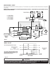
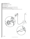
WARNING
Do not install or operate this fi re-
place through a switch wired in the
120 VAC or 240 VAC circuits. The
only approved wiring for a switch
is through the low voltage circuit
(24 VAC) as shown on Page 14.
Table 1
Power Supply Wire Gage
Voltage Wire Gage Fuse
Rating
120 V 14 GA. 15 AMP
240 V 14 GA. 20 AMP
Wall Switch / Thermostat Wire Gage
Voltage Wire Gage
5 VOLTS 18 GAGE
DO NOT USE THIS APPLIANCE OUT-
DOORS. DO NOT EXPOSE FIREPLACE
TO THE ELEMENTS (SUCH AS RAIN,
ETC.).
THIS APPLIANCE IS NOT INTENDED
FOR USE IN BATHROOMS, LAUNDRY
AREAS OR SIMILAR INDOOR LOCA-
TIONS. NEVER LOCATE THIS APPLI-
ANCE WHERE IT COULD FALL INTO
A BATHTUB OR OTHER WATER CON-
TAINER.
DO NOT RUN ELECTRICAL WIRING OR
POWER CORD UNDER CARPETING. OR
COVER WITH THROW RUGS, RUNNERS
OR SIMILAR MATERIALS.
FOR 120 VAC POWER CORD AVOID THE
USE OF AN EXTENSION CORD BECAUSE
THE EXTENSION CORD MAY OVERHEAT
AND CAUSE A RISK OF FIRE. HOW-
EVER, IF YOU HAVE TO USE AN EXTEN-
SION CORD, THE CORD SHALL BE NO.
14 AWG MINIMUM SIZE AND RATED
NOT LESS THAN 1800 WATTS, 15
AMPS. THE EXTENSION CORD MUST
BE A THREE CONDUCTOR SHEATH
CABLE WITH GROUNDING TYPE PLUG
AND CORD CONNECTION.
THIS APPLIANCE HAS HOT AND ARCING
OR SPARKING PARTS INSIDE. DO NOT
USE IT IN AREAS WHERE GASOLINE,
PAINT OR FLAMMABLE LIQUIDS ARE
USED OR STORED.
THIS FIREPLACE SHOULD NOT BE USED
AS A DRYING RACK FOR CLOTHING, NOR
SHOULD CHRISTMAS STOCKINGS OR
OTHER DECORATIONS BE HUNG NEAR IT.
USE THIS APPLIANCE ONLY AS
DESCRIBED IN THIS MANUAL. ANY
OTHER USE IS NOT RECOMMENDED BY
THE MANUFACTURER AND MAY CAUSE
A FIRE, ELECTRIC SHOCK OR INJURY
TO PERSONS.
IF APPLIANCE IS TO BE DISCON-
NECTED, TURN OFF CONTROLS FIRST.
DO NOT INSERT OR ALLOW FOREIGN
OBJECTS TO ENTER ANY VENTILATION
OR EXHAUST OPENING, AS THIS MAY
CAUSE AN ELECTRIC SHOCK, FIRE, OR
DAMAGE TO THE APPLIANCE.
SAVE THESE INSTRUCTIONS.
GENERAL INFORMATION
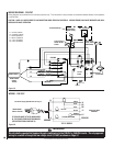
Power Supply Wire Specifi cations
120 Volt, 60 Hz, 1600 Watts:
(ref. Page 10)
Hard Wire Connection - Use two conductor,
non-metallic sheath cable with ground wire
(total three wires) for the incoming power
supply. The wire used must conform to local
and national electrical codes for the specifi ed
power consumption rating. See Table 1.
240 Volt, 60 Hz, 3000 Watt:
(ref. Page 11)
Use three conductor, non-metallic sheath cable
with ground wire (total four wires) for the
incoming power supply. The wire used must
conform to local and national electrical codes
for the specifi ed power consumption rating.
See Table 1.
Wall Switch or Wall Thermostat Kits
(optional kits, see Page 17)
Low voltage wire is provided for the wall switch
connection. The wires gage requirements are
shown on Table 1.