


12
these instructions can restrict the air flow required for proper
combustion, potentially resulting in fire, asphyxiation, serious
personal injury or death.
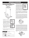
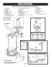
• Do not apply insulation to the top of the water heater, as this
will interfere with safe operation of the draft hood.
• Do not cover the outer door, thermostat or temperature &
pressure relief valve.
• Do not allow insulation to come within 2” (50.8 mm) of the
floor to prevent blockage of combustion air flow to the burner.
• Do not cover the instruction manual. Keep it on the side of
the water heater or nearby for future reference.
• Do obtain new warning and instruction labels from Maytag
for placement on the blanket directly over the existing labels.
• Do inspect the insulation blanket frequently to make certain
it does not sag, thereby obstructing combustion air flow.
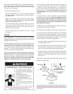
Combustion Air and Ventilation for
Appliances Located in Unconfined Spaces
UNCONFINED SPACE is space whose volume is not less than
50 cubic feet per 1,000 Btu per hour (4.8 m
3
per kW) of the
aggregate input rating of all appliances installed in that space.
Rooms communicating directly with the space in which the
appliances are installed, through openings not furnished with
doors, are considered a part of the unconfined space.
In unconfined spaces in buildings, infiltration may be adequate
to provide air for combustion, ventilation and dilution of flue
gases. However, in buildings of tight construction (for example,
weather stripping, heavily insulated, caulked, vapor barrier, etc.),
additional air may need to be provided using the methods
described in Combustion Air and Ventilation for Appliances
Located in Confined Spaces.
Combustion Air and Ventilation for
Appliances Located in Confined Spaces
CONFINED SPACE is a space whose volume is less than
50 cubic feet per 1,000 Btu per hour (4.8 m
3
per kW) of the
aggregate input rating of all appliances installed in that space.
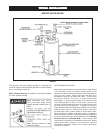
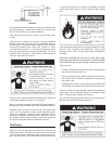
A. ALL AIR FROM INSIDE BUILDINGS:
(See Figures 10 and 11)
The confined space shall be provided with two permanent
openings communicating directly with an additional room(s)
of sufficient volume so that the combined volume of all spaces
meets the criteria for an unconfined space. The total input of
all gas utilization equipment installed in the combined space
shall be considered in making this determination. Each
opening shall have a minimum free area of one square inch
per 1,000 Btu per hour (22 cm
2
/kW) of the total input rating of all
gas utilization equipment in the confined space, but not less
than 100 square inches (645 cm
2
). One opening shall
commence within 12 inches (30 cm) of the top and one
commencing within 12 inches (30 cm) of the bottom of the
enclosures.
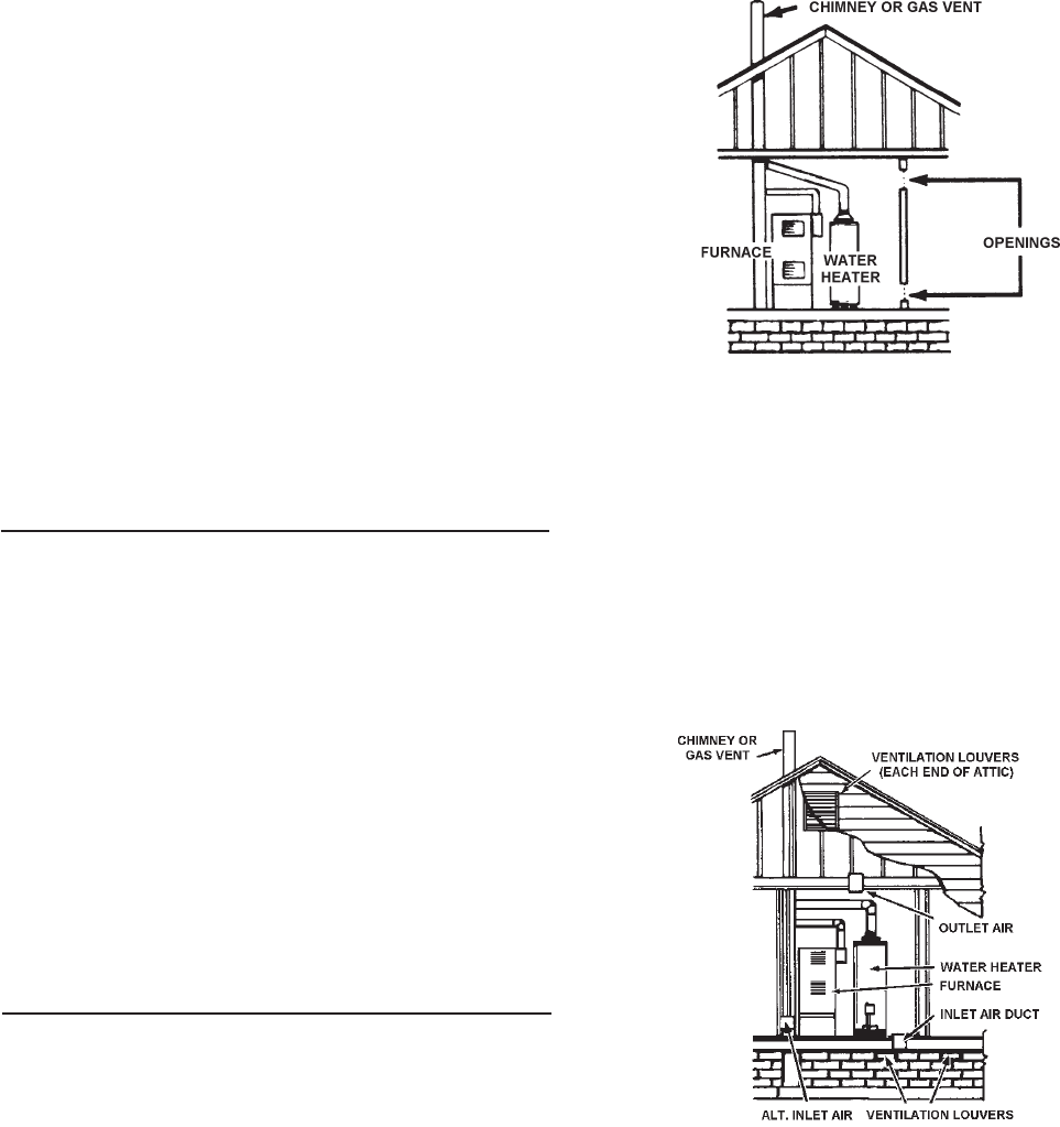
FIGURE 11.
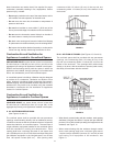
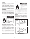
B. ALL AIR FROM OUTDOORS: (See Figures 12, 13 and 14)
The confined space shall be provided with two permanent
openings, one commencing within 12 inches (30 cm) of the
top and one commencing within 12 inches (30 cm) from the
bottom of the enclosure. The openings shall communicate
directly, or by ducts, with the outdoors or spaces (crawl or attic)
that freely communicate with the outdoors.
FIGURE 12.
• When directly communicating with the outdoors, each opening
shall have a minimum free area of 1 square inch per 4,000 Btu
per hour (5.5 cm
2
/kW) of total input rating of all equipment in the
enclosure, see Figure 12.
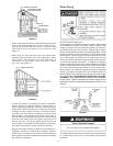
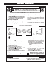
• When communicating with the outdoors through vertical
ducts, each opening shall have a minimum free area of
1 square inch per 4,000 BTU per hour (5.5 cm
2
/kW) of total
input rating of all equipment in the enclosure, see
Figure 13.