


Low temperature burners - INDITHERM
®
www.maxoncorp.com
combustion systems for industry
MAXON reserves the right to alter specifications and data without prior notice.
© 2008 Copyright Maxon Corporation. All rights reserved.
1-2.3-11
E-m-7/08
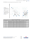
Flame supervision
Flame supervision can be accomplished by use of a UV-scanner for all INDITHERM
®
burners and sizes. The scanner connection
is 1”. Due to the presence of gas at the scanner port, only tight scanners can be used.
The use of a flame rod is only possible in a limited range of applications where the standard discharge sleeve is used. A flame rod
combined with a high temperature discharge sleeve would generate a flame signal too low for proper flame scanning.
Contact MAXON for more details when considering a flame rod.
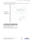
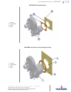
Flame development
INDITHERM
®
burners shall be installed in combustion chambers that allow full development of the burner flame.
Consult MAXON for proper combustion chamber lay-out.
Gas pipe train design
The INDITHERM
®
burner is very sensitive to variations in gas pressures at burner gas inlet. The burner gas inlet pressure should
not vary more then 2.5 mbar between high and low capacity.
Process back pressures
The INDITHERM
®
burner can operate between 0 and 1.5 mbar back pressure. The burner should not be used on applications
where back pressures would fall outside these limits. It is possible to mount the burner on a process with changing back pressures
as long as the fluctuating pressures stay within the 0 to 1.5 mbar limit.
Measuring equipment for burner commissioning
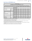
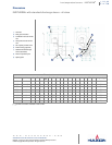
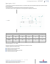
The burner gas pressures and air pressures as mentioned in table on page 1-2.3-6 should be used as a guideline for burner
system design and to have an approximative value for burner set up.To adjust the burner properly during commissioning, the
oxygen content in the flue gas should be measured. A properly adjusted burner in an indirect fired application should have
approximately 3% O
2
in the stack at maximum capacity.