


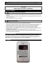
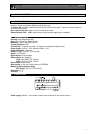

Operating Instructions for Master-Bilt Alarm/Light Module (19-14009)
1598003200
7
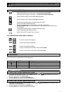
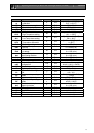
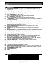
14. PARAMETER LIST
Ot Thermostat probe calibration: (-12.0
÷12.0°C/ -21÷21°F) allows to adjust possible offset of the
thermostat probe.
CF T measurement unit: °C = Celsius; °F = Fahrenheit. When the measurement unit is changed the
Set Point and the values of some parameters have to be modified.
rES Resolution (for °C): (in = 1°C; dE = 0.1 °C) allows decimal point display.
Ut Display update: The time delay of the T readout (0÷255s)
onF Off function enabling: n = off function disabled; y = off function enabled;
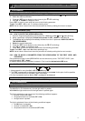
ALU High T° alarm setting: (ALL
÷ 150°C or 302°F);
when this T° is reached and after the ALd delay time the HA alarm is enabled.
ALL Low T° alarm setting: (- 50°C or -58°F
÷ ALU)
when this T° is reached and after the ALd delay time, the LA alarm is enabled,.
AFH T° alarm differential: (0,1÷25,5°C; 1÷45°F) differential for T° alarm Set Point and fan regulation Set
Point, always a positive value
ALd T° alarm delay: (0÷255 min) time interval between the detection of an alarm condition and the
corresponding alarm signaling.
dAO Delay of T° alarm at start-up: (0min÷23h 50min) time interval between the detection of the T°
alarm condition after the instrument power on and the alarm signaling.
EdA Alarm delay at the end of defrost: (0
÷255 min) Time interval between the detection of the T° alarm
condition at the end of defrost and the alarm signaling.
dot Delay of T° alarm after closing the door: (0
÷255 min) Time delay to signal the T° alarm
condition after closing the door.
LHt Light timer: (0-255 min) The time the light will stay on after pressing the light switch on the
keyboard.
doA Open door alarm delay:(0÷255 min) delay between the detection of the open door condition and its
alarm signaling: the flashing message “dA” is displayed.
oA1 First relay configuration: (14-15): ALr = alarm; LHt = light; onF = on/off relay
oA2 Second relay configuration: (14-16): ALr = alarm; LHt = light; onF = on/off relay
AOP Alarm relay polarity: cL = closing contacts; oP = opening contacts.
i1P Digital input 1 polarity (1-2): CL : the digital input is activated by closing the contact;
OP the digital input is activated by opening the contact
i1L Door switch to turn light ON(1-2): (y / no) To turn the light ON automatically when the door is
open. The light will turn off based on LHt . Keyboard switch must be turned ON first.
i1F Digital input 1 operating mode(1-2): EAL = external alarm; dor = door switch; dFr = A defrost is
running; LHt = keep light ON (signal from occupancy sensor) override LHt.;
i2P Digital input 2 polarity (1-3): CL : the digital input is activated by closing the contact;
OP the digital input is activated by opening the contact
i2F Digital input 2 operating mode: configure the digital input function:
EAL = External alarm;
PAn =Panic alarm;
dFr = A defrost is running;
LHt = Keep light ON (signal from occupancy sensor) override LHt.
did Time interval/delay for digital input alarm:(0
÷255 min.) If I2F=EAL or PAn (external alarms), “did”
parameter defines the time delay between the detection and the successive signaling of the alarm.
tbA Alarm relay & Buzzer disabling: (y ; no)
Pbc Type of probe (PTC, NTC)
dP1 Probe 1 T
rEL Software release for internal use.
Ptb Parameter table code: read only.
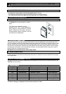
15. PARTS LIST
M/B Part Number Description
19-14009 WI therm, alarm, panic light, contl. #XWA11V-4N1F0
19-14012 PROBE, 18NB-NTC-1.5M, (5')
19-14013 PROBE, 18NB-NTC-1.5M, (50')
19-14014 PROBE, 18NB-NTC-1.5M, (75')
For more information, please contact our Technical Service Dept.
@ 1-800-684-8988