


23D8036 19
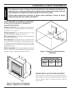
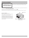
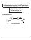
ELECTRICAL WIRING (MILLI-VOLT)
The milli-volt valve is a self-powered combination gas control
THAT DOES NOT REQUIRE 110 VAC TO OPERATE.
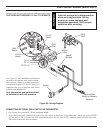
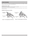
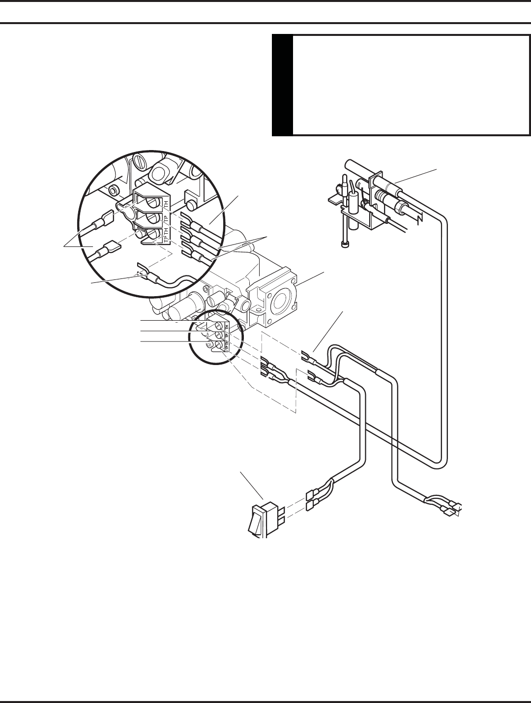
Figure 20 - Wiring Diagram
Optional Wall
Switch or Remote
Receiver
Switch
On/Off
Switch
On/Off
Switch
Wall
Switch
ODS
Pilot
Millivolt
Valve
TH = 3
TP = 1
TP/TH = 2
ODS
Pilot
Spade
Terminal
Label all wires prior to disconnection
when servicing controls. Wiring
errors can cause improper and
dangerous operation. Verify proper
operation after servicing.
WARNING
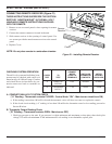
CONNECTING OPTIONAL WALL SWITCH OR THERMOSTAT
1. Use 18 awg, two-wire cable, 15 feet maximum length.
2. At one end of the cable, connect both wires to the wall switch or thermostat. At the other end, connect one wire to TP/TH
and one wire to TH, or connect the wall switch/thermostat to the two male (0.25") terminals on the left side of the unit.
The color of the wires does not matter.
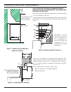
See Figure 20 and installation instructions
provided with optional wall switch, thermo-
stat or remote control for wiring instructions.
A maximum length of 15 feet of 18awg two
conductor wire is to be used for wall switch
or thermostat installations.
Note thermostats and switches must
be suitable for milli-volt operation.