


4. Run power supply cable through the connector, leaving about 8” of
wire inside the box.
5. Connect the supply cable ground wire to green ground screw provided.
NOTE: Lead holes for a #8 sheet metal screw have been provided in the
sides of the back box.. After the finished wall or ceiling has been put up,
drive a # 8(m4) sheet metal screw (recommended 1” long) through the
side of the box not mounted to the stud. This will prevent the back box
from pulling out when installing the heater assembly. (See Figure 1)
INSTALLATION OF BACK BOX
IN EXISTING CONSTRUCTION
(WALL OR CEILING)
1. Carefully mark and cut a hole measuring 9-3/8" (235mm) wide by 11-
1/8" (283mm) long. One edge of the hole must be cut along the
edge of a stud.
2. Proceed to No. 1 through 5 (Installation of Wall Box in New
Construction).
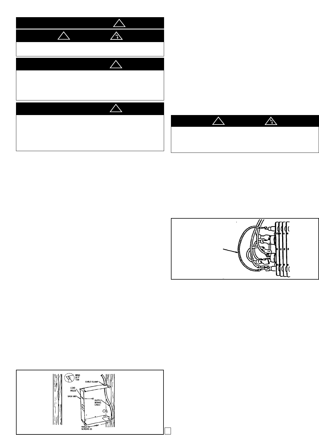
FIELD CONVERSION FOR LOWER WATTAGE RATING
NOTE: Refer to specification chart for lower wattage ratings which are
available.
To convert heater to lower wattage rating, completely remove red jumper
wire from both heating elements (See Figure 2). Discard this jumper. Be
sure remaining wires are securely connected.
INSTALLATION AND WIRING
OF HEATER / FAN ASSEMBLY
1. Following wiring diagram (Figure 3) connect supply wiring to heater
leadwires in back box.
NOTE: For 120 and 277 volt heaters connect the white neutral supply
lead to the heaters white pigtail lead, and connect the black supply lead
to the heater black pigtail lead. For 208 and 240 volt heaters change the
color of the heaters white pigtail lead to black by wrapping with black elec-
trical tape. (Most electrical codes require the supply leads to be con-
nected to black leads). Then connect the two black supply leads to the
two black receptacle leads.
2. Secure supply ground wire under green ground screw in back box.
3. Slide supply wiring under retaining straps in back box to hold in
place.
4. Insert wiring plug from heater/fan assembly into socket in back box.
5. Fit heater/fan assembly into back box and secure in place with (2)
screws provided through the center slots in the fan assembly.
NOTE: Use the screws provided by the factory to install fan deck to
the back box.
GENERAL
The heater is designed for recessed installation in 2” X 4” (50mm X
101mm) stud or larger wall or ceiling sections using the wall box provid-
ed. The heater may also be surface mounted by using the Surface
Mounting Frame, Model SRASM or semi-recess mounted by using a
SRAS1 (for 1” (25 mm) recess frame) or a SRAS2 (for 2” (50mm) recess
frame). All three accessories are ordered separately. The heater may be
wired with standard building wire (60°C). Refer to specification chart (see
pg. 4) for correct supply voltage and wire size.
NOTE: The optimum mounting height for this heater is 18" to 24" (450 to
600mm) from floor to bottom of back box. Do not install closer than
2”(50mm) from the floor. Back box may be mounted such that discharge
portion of grille can be oriented down, left, right, or up.
For surface or semi-recess mounting, consult Installation Instructions
packed with SRASM, SRAS1, SRAS2
INSTALLATION OF WALL BOX
IN NEW CONSTRUCTION
(WALL OR CEILING)
NOTE: If the finished wall surface is already up, follow instructions for
“INSTALLATION OF BACK BOX IN EXISTING CONSTRUCTION”.
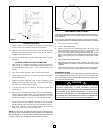
1. Determine which side of the back box is to be mounted against a
stud and bend the tabs at the rear corners out 90 degrees so that
the back box will be square with the stud after installation. (See
Figure 1).
2. Remove one of the knockouts on socket side of the back box and
install a cable or conduit connector.
3. Position back box against side of studs and secure using nails or screws
as shown in Figure 1.
NOTE: The back box must be installed with the front edge flush with the fin-
ished surface.
Figure 2
AN ELECTRICAL SHOCK, FIRE OR WATER DAMAGE COULD
RESULT IF WIRING OR PIPING IS DAMAGED DURING CUTTING.
MAKE SURE ALL WIRING AND PIPING ARE CLEAR OF AREA
BEFORE CUTTING.
THE HEATER IS HOT WHEN IN USE. DO NOT INSTALL THE
HEATER BEHIND DOOR, BEHIND TOWEL RACK, IN CLOSET,
WHERE CURTAINS OR DRAPES COULD TOUCH OR BECOME
SCORCHED BY HEATER, OR WHERE AIRFLOW TO HEATER MAY
BE OBSTRUCTED. KEEP ELECTRICAL CORDS, BEDDING, FURNI-
TURE AND OTHER COMBUSTIBLES AWAY FROM HEATER.
FOR WALL MOUNTING, DO NOT INSTALL HEATER CLOSER THAN
2" (51mm) TO THE FLOOR OR ANY ADJACENT WALL SURFACE. DO
NOT INSTALL CLOSER THAN 36" (915mm) TO THE CEILING. FOR
CEILING MOUNTING, DO NOT INSTALL CLOSER THAN 12” (304mm)
TO ADJACENT WALL.
TO PREVENT HAZARD OF FIRE OR ELECTRICAL SHOCK, DO NOT
INSTALL WITHOUT BACK BOX.
CAUTION
IMPORTANT
WARNING
CAUTION
CAUTION
2
Figure 1
Remove red
jumper for
lower wattage
rating
!
!
!
!
!