


Installation
1. Using template provided, determine mounting
location.
2. Drill holes and attach mounting hardware (not
included).
IMPORTANT: THE HARDWARE AND THE
SUPPORTING STRUCTURE MUST BE CAPABLE OF
SUPPORTING A MINIMUM 150 LB. LOAD.
NOTE: All installation should be done to meet local
building code
.
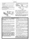
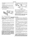
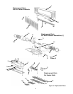
3. Mount cabinet on wall and securely tighten hardware.
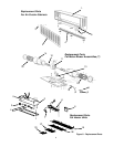
4. Replace motor/blower assembly in cabinet. Secure
two wing nuts on blower base. Reconnect motor
electric cord plug assembly and heater plug.
5. Replace intake grille with louvers facing down and
refasten knurled nuts.
FIELD POWER WIRING
WARNING: ALL AIR CURTAINS SHOULD BE
INSTALLED BY QUALIFIED PERSONNEL
.
1. Before wiring, be sure that available power supply,
voltage, phase, and frequency corresponds to that
specified on heater rating plate. In addition, make cer-
tain that service capacity is sufficient to handle load
imposed by the equipment.
2. Install all wiring, protection and grounding in accor-
dance with the National Electrical Code (NEC) and
all local requirements.
WARNING: THIS FAN HAS AN INTERNAL SELF
RESETTING THERMAL OVERLOAD PROTECTOR.
ALWAYS DISCONNECT FROM POWER SUPPLY
BEFORE SERVICING.
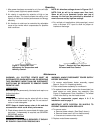
3. Remove two screws from switch box and remove
cover.
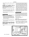
4. Run proper size copper power supply conductors from
the field power supply disconnects, (supplied by
others) with insulation rated minimum 75˚C (167.0˚F).
One set of conductors from 240VAC, 50/60Hz supply
source shall be routed through the 3/4 inch conduit
knockout, using a suitable knockout connected to the
contactor contact terminals marked L1, L2. A
separated set of supply conductors from a 120VAC,
50/60 Hz supply source shall be routed through 1/2
inch knockout using a suitable knockout connector, for
connection of the fan circuit. The fan supply
conductors are to be marked L1, N (see diagram on
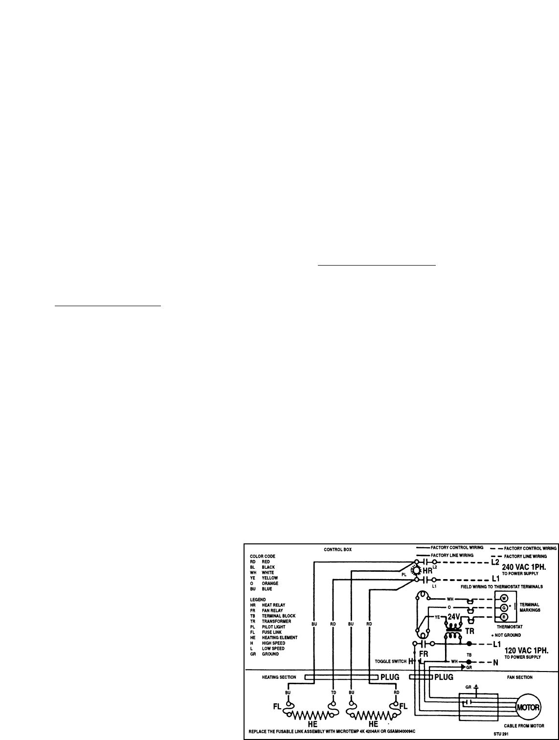
inside heater wiring compartment cover and Figure 5).
5. The heater control box must have an unbroken
electrical ground to minimize personal injury if an
electrical fault should occur.
FIELD CONTROL WIRING
Electric heater is equipped with a step-down transformer
for 24V control circuit. Thermostat model number RSV-
130-R-54 must be used to energize heater with the fan
motor. Connect thermostat wiring from thermostat to
control leads in heated air curtain control box by means
of conduit or equivalent. A 1/2 inch knockout is provided.
Class1 wiring is required.
6. Replace heater control box cover.
7. Unit is ready for operation.
8. Restore power.
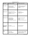
NOTE: Air curtain has high/low selector switch. See
Operation section for proper setting instructions.
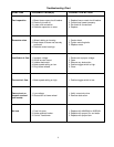
9. Upon completion of all installation, inspect unit for
excessive vibration during operation. If excessive
vibration is noticeable, disconnect power supply.
Inspect mounting installation and refer to
Troubleshooting Chart for probable cause.
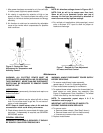
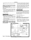
Figure 5 - Wiring Diagram