Universal Thermostat Kit
Installation Instructions
FOR USE WITH DISPENSERS ONLY
THIS CONTROL KIT IS INTENDED TO REDUCE OVERFILL AND CONDENSATION ISSUES
1. Remove all ice from dispenser.
2. Disconnect all power to the ice machine and
dispenser at the service disconnect or fuse/breaker
panel.
3. Move the ice machine and dispenser away from
the wall for easier access.
4. Remove all panels and control box cover.
5. If an ice machine is already installed on the
dispenser, raise and support the right side of the
ice machine. Install the mounting bracket on the
right-hand side of the dispenser 6” from the right
rear corner. Compress the bracket to the thickness
of the dispenser wall and tighten the two screws.
6. Route thermistor wire out back of the ice
machine/dispenser (lower the ice machine, if
supported). Remove unused knockout on the ice
machine back panel, install romex connector and
route wire into the ice machine compressor
compartment.
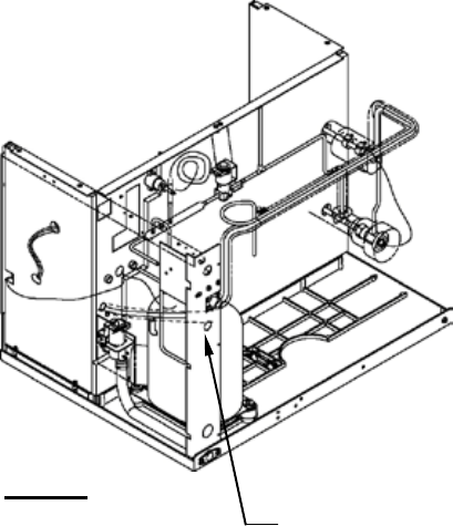
7. Normally the controller can be mounted on the
bulkhead flange. If not, a suitable area must be
found for your model. Use controller bracket to
locate mounting holes on the flange of the
bulkhead. Drill two 9/32" diameter holes (used to
mount the controller bracket - see View A). Do
not mount the controller, at this time.
8. Route the four wires from the temperature control
to the control box (insuring that the wires will not
come in contact with any refrigeration tubing).
IMPORTANT:
The thermostat must be wired to match the voltage
of the ice machine. The thermostat is pre-wired for
115 volts. Rewire thermostat, if your ice machine is
240 volts.
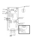
9. The control box line voltage wiring offers two options:
· Connect thermostat L1 (brown) and L2 (blue) wires
to contactor (incoming line voltage side) L1 and L2.
OR
· Disconnect incoming power line wire nuts.
Remove quick-connect fittings from brown and
blue wires and strip 1/2” of insulation from the
wires. Connect incoming power L1, ice machine
L1, and thermostat L1 (brown) wires together with
wire nut. Connect incoming power L2, ice machine
L2, and thermostat L2 (blue) wires together with
wire nut.
10. Disconnect the red male/female connector bin switch
wire and connect the red male wire from the controller
to the red female bin switch wire.
11. Connect the white male bin switch wire to the white
female wire of the controller.
12. Restore all power to the ice machine and the dispenser
at the service-disconnect or fuse/breaker panel.
13. The factory setting on the thermostat will be correct for
most applications. Adjust only when necessary.
14. With two screws, secure the controller bracket
assembly to the flange of the bulkhead.
15. Reinstall the control box cover and all panels.
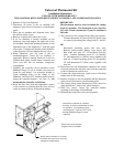
View A
Position the controller in a suitable
location. It can be installed here on most
ice machines. Use bracket to locate
mounting holes - drill two 9/32" holes
through bulkhead flange to secure
controller
Route sensor wire between
dispenser and ice machine
Install romex connector in a vacant
knockout and route sensor wire into
compressor compartment


