


6
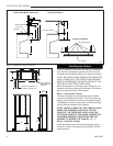
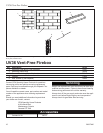
UV36 Vent-Free Firebox
20007446
21"
14"
1/2"
36"
36"
32"
14"
Min.
36"
T143
framing dimension
11/4/03 djt
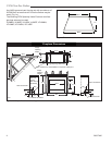
2” Minimum Clearance to
Side Wall or Mantel Leg
1/2” Clearance
Not Required at
this Point
Fig. 4 Framing dimensions.
Installing the Firebox
This list of specific instructions will help you make cer-
tain that every installation operation is done correctly.
Complete the installation steps in the sequence shown.
LOCAL BUILDING CODES SHOULD BE CONSULTED
IN ALL CASES AS TO THE PARTICULAR REQUIRE-
MENTS CONCERNING THE INSTALLATION OF FAC-
TORY BUILT VENT FREE FIREPLACES.
Select the location for the fireplace by taking into con-
sideration the factors previously outlined in the Choos-
ing the Location section of this manual.
Step 1: Framing the Firebox
The entire fireplace can be elevated above the floor
to achieve a raised hearth effect. This can be done by
adding a small platform to achieve the desired height.
This platform must be a continuous surface extending
the full width and depth of the fireplace.
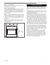
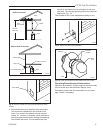
STOP! INSTALL CANOPY AT THIS TIME BY LOOS
-
ENING THE SCREWS LOCATED AT THE TOP
FRONT OF THE FIREPLACE. NEXT, SLIDE THE
SLOTTED FLANGE OF THE CANOPY UNDER THE
LOOSENED SCREWS, THEN RETIGHTEN THE
SCREWS TO SECURE THE CANOPY. (Fig. 3)
Step 2: Install the Firebox
Install the firebox into the framed opening by setting
it directly in front of the opening and sliding it into the
proper position.
T233
clearances
2/04
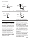
17"
8"
6"
1"
9"
12"
20"
24"
9"
3"
12"
21"
Noncombustible
or Void
Standoff
Noncombustible
T233
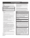
Fig. 3 Combustible mantel clearances.
Cabinet Installation
Combustible Mantel Clearances
Canopy Installation
Canopy
Hex Head Screws